1.0 Technical Specifications
1.1 Electrical
Operating Voltage Range: 12-48V operating range (9
to 60VDC), 35mA (typ., CAN inactive)
1.2 Mechanical
Display: LCD with 10 segment bar and 5 digit numeric
(5mm high);
Warning LED
Hardware: Mounting bracket (see section 2.0)
Panel Cutout: 52mm / 2 1/16” diameter
1.3 Environmental
Operating Temperature:-40C to +85C
Storage Temperature:–50C to +90C
Humidity: 95% RH (non-condensing) at +38C
Shock: SAE J 1378 March 83 Amplitude 44-55g, half
sine, 9-13ms duration
Vibration: SAE J 1378 Double amplitude of 1.53mm
with frequency sweep for 10-80-10Hz (20g max) at 1
minute intervals
Sealing: IP65 front, IP65 rear (with connector installed)
2.0 Installation
2.1 Terminal Assignments
2.2 Mounting
Caution! Bracket is placed over gauge in reverse fashion
for ease of shipping. Remove bracket from gauge, install
gauge into mounting hole and place mounting bracket
over gauge in reverse order from the shipped position.
Rotate gauge to proper orientation and push the bracket
against the back panel to secure the gauge. Note: Bracket
has been designed to remain secured to the gauge after
proper installation. Attempts to remove the bracket after
installation may result in damage to the bracket.
See Dimensional Drawing on reverse side of page.
2.3 Interconnect
Curtis 3100R gauge mates with a 4 pin AMP
connector P/N 794805-1,
interface seal P/N 794772-4, wire seal P/N 794758-1,
Pins P/N 770904-X for #18-24 AWG
3.0 Operation
3.1 With Curtis Motor Controllers
Upon initial power up, all display segments are
illuminated for 1 second and then turned off. The
unit is then ready to received CAN messages. The
basic 3100R is a passive communication device and
simply waits to receive / display CAN messages from
Curtis Model 1236 or 1238 motor controllers. A single,
red LED can be illuminated to indicate warning /
diagnostic conditions.
Optional buttons (2) are used to send CAN messages
to the motor controller. Each button sends a specic
CAN message to the controller. VCL (Vehicle Control
Language) resident in the motor controller can be
used to dene a specic response to each button.
3.2 With Curtis Acuity Battery Monitoring System
When Model 3100R is connected only to a Curtis
Acuity, the 3100R serves as the communication
master. After all display segments are illuminated at
initial power up, the numeric section of the LCD will
display, in sequence, the following battery information
from the Acuity:
xVoltage (bAt)
xCurrent (I)
xTemperature (t)
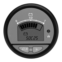
xState-of-Charge (SOC)
xAmpere Hours into the battery (AHrs C)
xAmpere Hours out of the battery (AHrs d)
xEstimated remaining battery capacity (Ebc)
Following this sequence, the LCD will return to the
default screen of displaying battery state-of-charge
in the bargraph and battery voltage in the numeric.
The only time the bargraph does not display state-of-
charge is when Estimated remaining battery capacity
is displayed.
3100R Instructions
Without buttonsWith buttons
J1 external Description
Pin 1 B– Common voltage return
Pin 2 B+ + volts / 50 mA max current
Pin 3 CAN HI CANOpen
Pin 4 CAN LO
Read Instructions Carefully!