EasyManua.ls Logo

Curtis PCGT5 - User Manual

Curtis PCGT5
8 pages
To Next Page IconTo Next Page
Loading...
1
3. Plug the power cord into an electrical outlet rated at 20A.
4. Turn on power at the toggle switch behind the unit. The lights (display window and row of but-
tons) on the front door will activate and the heating tank will start to ll.
5. Water in the heating tank will require about one hour to reach operating temperature (factory
setting of 190°F). At this time the LCD will display “READY TO DISPENSE”.
6. Remove and ll the canisters with powdered cappuccino product.
Your Curtis G3 System is Factory Pre-Set and Ready to Go, Right from the Box.
Following are the Factory Settings for your Primo Cappuccino Beverage System:
Tank Temperature = 190°F
Flavor Controls= Set at 60%
Dispensing Mode Set for Manual Dispensing
Generally there will never be a reason to change your G3 programming. However, should you need
to make slight adjustments to meet your dispensing needs, programming instructions are provided
later in this manual.
System Requirements:
Water Source 20 – 90 PSI (Minimum Flow Rate of 1 GPM)
Electrical: See electrical schematic on page 7.
Models Included
• PCGT4
• PCGT5
CAUTION: DO NOT
connect the unit to hot
water. The inlet valve is
not rated for hot water.
CAUTION: Follow this
setup procedure before
attempting to use this
unit. Failure to follow these instruc-
tions can result in injury and/or void
of warranty.
CAUTION: Equipment
must be installed to
comply with applicable
federal, state, and local plumbing/
electrical codes having jurisdiction.
Important Safeguards/Symbols
This appliance is designed for commercial use. Any servicing other than cleaning and routine main-
tenance should be performed by an authorized Wilbur Curtis Co., Inc. service technician.
DO NOT immerse the unit in water or any other liquid
To reduce the risk of re or electric shock, DO NOT open service panels. There are no user
serviceable parts inside.
Keep hands and other items away from hot areas of the unit during operation.
Never clean with scouring powders or harsh chemicals.
Wilbur Curtis Co., inC.
Service Manual – PCGT4 & PCGT5
Symbols
WARNINGS – To help avoid personal injury
Important Notes/Cautions – from the factory
Sanitation Requirements
NSF International requires the following water connection:
1. A quick disconnect or additional coiled tubing (at least 2x the depth of the unit) so that the machine
can be moved for cleaning underneath.
2. This equipment is to be installed with adequate backow protection to comply with applicable
federal, state and local codes..
3. Water pipe connections and xtures directly connected to a potable water supply shall be sized,
installed and maintained in accordance with federal, state, and local codes.
SETUP STEPS
1. The unit should be level (left to right - front to back), on a secure surface.
2. Connect the water line to the water inlet tting on the rear of the unit. Water volume going to the
machine should be consistent. Use tubing sized sufciently to provide a minimum ow rate of
one gallon per minute.
NOTE: A water ltration system must be used to help maintain trouble-free operation. Air must
be purged from the cartridge prior to connection to equipment. In areas with extremely
hard water, we highly recommend the use of a Curtis approved water lter. For our full line of
lters, please log on to www.wilburcurtis.com.
ISO 9001:2008 REGISTERED
WILBUR CURTIS CO., INC.
6913 Acco Street,
Montebello, CA 90640-5403
For the latest information go to
www.wilburcurtis.com
Tel: 800/421-6150
Fax: 323/837-2410
FOR THE LATEST SPECIFICATIONS AND INFORMATION GO TO WWW.WILBURCURTIS.COM
Technical support: 1-800-995-0417. M-F 5:30am-4:00pm PST.
Email: techsupport@wilburcurtis.com

Other manuals for Curtis PCGT5

Question and Answer IconNeed help?

Do you have a question about the Curtis PCGT5 and is the answer not in the manual?

Curtis PCGT5 Specifications

General IconGeneral
BrandCurtis
ModelPCGT5
CategoryBeverage Dispenser
LanguageEnglish

Summary

Important Safeguards and Symbols

Symbols

Symbols used to highlight warnings and important notes from the factory.

Sanitation Requirements

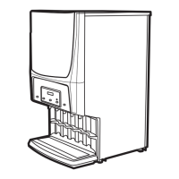
Factory settings and requirements for the Primo Cappuccino Beverage System.

Setup Steps

Water Inlet Connection

Connect water line, ensure flow rate, and adhere to NSF connection requirements.

Power Connection and Activation

Connect power cord to 20A outlet and turn on unit via toggle switch.

Heating and Dispense Readiness

Wait for heating, monitor LCD for readiness, and fill product canisters.

Operating Instructions

Choose Flavor and Dispense

Select a flavor, place cup under spout, and push dispensing button.

Fill Canisters Daily

Canister Removal and Refilling

Remove canisters, refill with product, and reattach them to the unit.

Cleaning Procedures

Cleaning Frequency and Warnings

Warnings against chlorine products; schedules for cleaning every 3-4 hours, daily, and weekly.

Daily Cleaning

Wipe exterior, clean drip drawer, louvered screen, and dispensing area.

Weekly Cleaning

Clean whipper assembly parts, mounting plate, and water inlet fitting.

Propeller and Shaft Seal Alignment

Properly align the propeller with the 'D' embossed on the motor shaft for correct seating.

Programming Guide

Entering Programming Menus

Press and hold STOP/WASH for ten seconds to enter the Program Menus.

Manual Dispense Programming

Select stations for manual dispensing, saving completion messages appear.

Dispense By Time Programming

Set dispense time for selected stations, saving time after dispense.

Temperature Programming

Adjust tank temperature from 80°F to 204°F in 2-degree increments.

Powder % Ratio Programming

Adjust powder ratio from 0% to 100% in 5% increments for product strength.

Service Call Programming

Program a service phone number displayed during errors like SENSOR or WATER ERROR.

Banner Name Programming

Program up to 14 letters for company or regional name; blanking disables the feature.

Model Select Programming

Select the desired model (PC-1 through PC-5) to set and exit program mode.

Exit Programming

Select to exit program mode and return the unit to normal operation.

Parts List

Component Identification

List of parts with item numbers, part numbers, and descriptions for PCGT4/5 models.

Canister Configuration

Canister Type and Quantity

Specifies the type and quantity of canisters required for PCGT4 and PCGT5 models.

Electrical Diagram

Power Supply and Wiring

Diagram showing power supply, wiring, and connections for the unit's components.

UPM and UCM Connector Pin Assignments

Details pin assignments for Universal Power Module (UPM) and Universal Control Module (UCM).

Triac Pin Assignments

Defines the pin assignments for the Triac component in the electrical system.

Electrical Rating Table

Table showing electrical ratings (power, current) for US and Canadian models.

Product Warranty Information

Warranty Terms and Conditions

Details warranty periods for digital control boards, electrical components, and grinding burrs.

Conditions and Exceptions

Lists conditions and exceptions that void the warranty, including improper operation or installation.

Return Merchandise Authorization

Procedure for warranty claims, requiring prior authorization (RMA) before repair or return.

Related product manuals