www.cuttermasters.com - Toll Free (800) 417 2171
CUTTERMASTER Professional JXT User’s Manual
Page 20
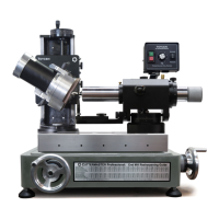
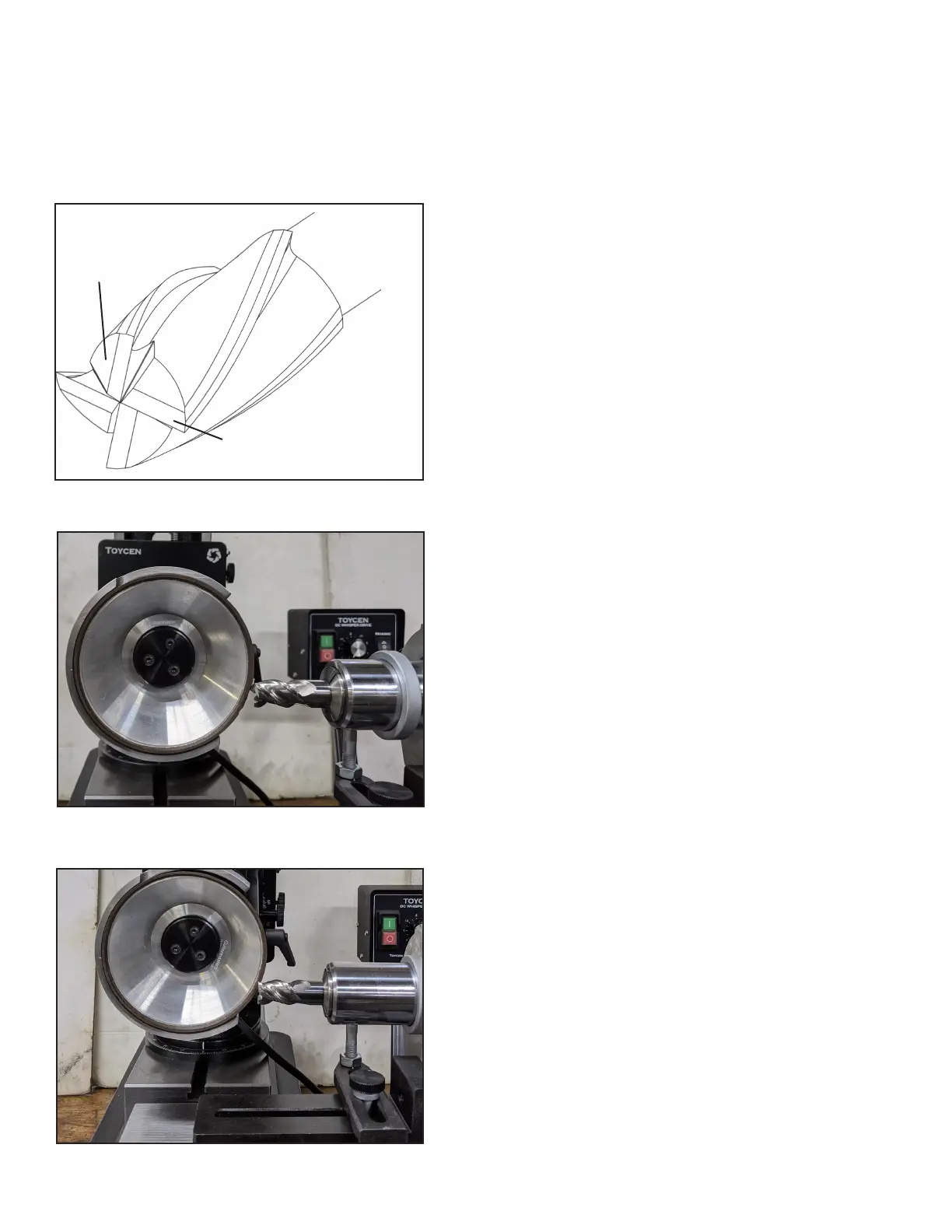
End Grinding the Secondary with Side of Wheel
End Grinding the Primary with Side of Wheel
3.2 Grinding the Ends of Standard End Mills: Primary and Secondary Angles
Side (O.D.) of Wheel Approach
Primary
Secondary
(clearance)
1. Set the motor height and angle. To grind the end,
or face, from the same setup as the preceding section,
3.1, begin by setting the motor/spindle angle to zero.
When the motor is set at zero, the air spindle center-
lineis1/2”belowthecenterlineofthegrindingwheel;
thisprovidesa7°clearanceangleooftheradiusof
thewheelo.d.Youcansharpentheendsofall2-ute,
3-ute,and4-utenoncentercuttingendmillsusing
this method.
2. Set the air bearing. Remove the stylus shelf from
the air bearing. It is not needed for ends. Set the air
bearingto2°tocreateadishintheend.Ifaatendis
desired set to 0°.
3. Time the tool to the index collar. Loosen the in-
dexingringandbringitushtothebackendoftheair
bearing housing. Push the indexing pin, which is on
the top center of the right side of the air bearing, into a
slot in the indexing ring that is marked with a number
thatmatchesthenumberofutesontheendmill.
Whileholdingtheindexcollarrmlyagainstthehous-
ing, push the spindle so that the end mill is past the
stylusatleast1/2’’,andthenalign2parallelutesuntil
they are square to the table. Tighten the set screw in
the index collar.
When you grind you will be maintaining steady pres-
sure of the index ring against the air bearing housing
so that the end mill is not pushed back when in con-
tact with the grinding wheel. Some users may prefer
to push the air bearing spindle all the way to the right,
settheutessquareand then lock theindexingring
in place, so that they don’t have to hold the air spin-
dle in place, however this will entail cranking the table
forward a distance to compensate, or the air bearing
forward by loosening the swivel base nut and sliding
the air bearing forward.
4. Position the wheel and tool using the x,y tables
and take rst grind. Maneuver the grinding wheel
with the y-axis handle so that the edge of the wheel
Youcansharpentheendsofall2-ute,3-ute,and4-utenoncentercuttingendmillsusingthismeth-
od.For4-utecentercuttingand6-utenoncentercuttingendmills,theendsmustbesharpenedoof
thefaceofthegrindingwheel,insteadofotheo.d.Seesection3.2