31. Attach Console.
A. Plug upper display cable into lower display
cable. See Figure 1. NOTE: Ensure cable
connectors are securely fastened.
B. Place the console in the correct position on
the main frame assembly and hand thread
each of the four BHSCS and washers. See
Figure 1. NOTE: Confirm that no cables are
pinched lowering the console.
C. Using a 7/32” Allen washer securely fasten
the four BHSCS.
32. Connect power and test for proper operation.
A. Turn the main power switch to the on (I)
position.
B. Test the unit to verify proper operation.
29. Reinstall left handle linkage rod.
A. Properly position the left handle linkage rod in
place.
B. Place a drop of loctite #242 on the SHCS that
will secure the left handle linkage rod and
place another drop of loctite into the shaft
(where the SHCS will be tightened into).
C. Using a 3/16” Allen wrench, install SHCS,
spacer, cap and washer (removed in steps
6A-6B) . See Figure 13. NOTE: SHCS must be
tightened to a minimumof 90 inch-pounds.
D. Repeat steps 29A-29C for right handle linkage
rod.
28. Reinstall Left arm handle.
A. Place Left arm handle in position and align
with holes on frame.
B. Insert pivot pin (removed in step 6D). See
Figure 4. NOTE: You may need a rubber
mallet to install the pivot pin.
C. Place a drop of loctite #242 on the BHSCS
(removed in step 6D). Place another drop of
loctite #242 inside pivot pin shaft (where the
BHSCS will be tightened into).
D. Using two 7/32” Allen wrenches, install the two
BHSCS and washers (removed in Step 6D).
See Figure 4.
E. Repeat steps 28A-28D for right arm handle.
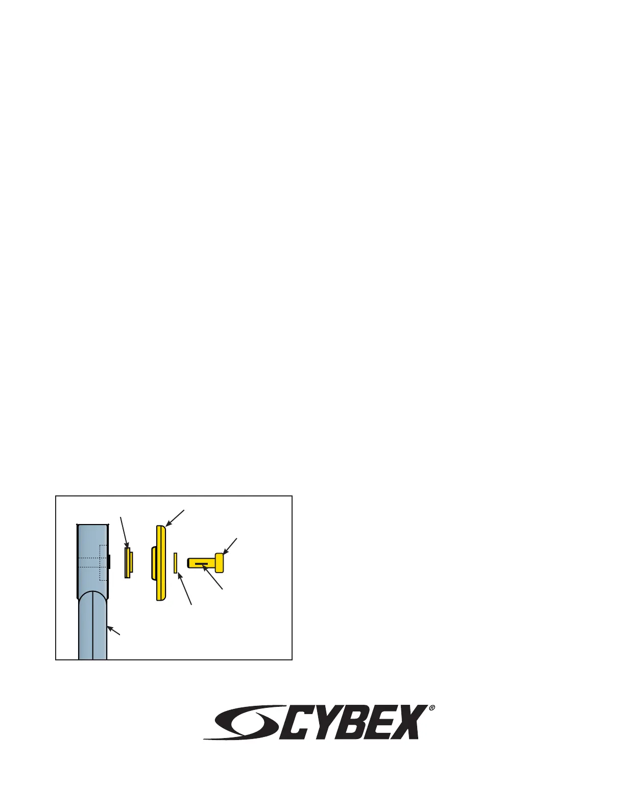
Spacer
Cap
Flat Washer
SHCS
Figure 13
Linkage Rod
loctite
30. Reinstall lower left linkage rod.
A. Properly position the lower left linkage rod in
place.
B. Place a drop of loctite #242 on the SHCS
that will secure the lower left linkage rod and
place another drop of loctite into the shaft
(where the SHCS will be tightened into).
C. Using a 3/16” Allen wrench, install SHCS,
spacer, cap and washer (removed in steps
5A-5B). See Figure 13. NOTE: SHCS must be
tightened to a minimum of 90 inch-pounds.
D. Repeat steps 30A-30C for lower right linkage
rod.
Cybex
®
and the Cybex logo are registered trademarks of Cybex International, Inc.
Arc Trainer
®
and its mark are registered trademarks of Cybex International, Inc.
10 Trotter Drive Medway, MA 02053 • 508-533-4300 • FAX 508-533-5183 • www.cybexinternational.com • techhelp@cybexintl.com
techpubs@cybexintl.com • Copyright © 2008, Cybex International, Inc. All rights reserved • 610A-404 B • March 2008
 Loading...