EasyManua.ls Logo

CYBEX Arc Trainer 610AK019-4 User Manual

CYBEX Arc Trainer 610AK019-4
5 pages
To Next Page IconTo Next Page
Page #1 background imageLoading...
Page #1 background image
Arc Trainer
®
Main Frame Assembly
Kit No. 610AK019-4
Kit No. 630AK019-4
Installation Instructions
NOTE: This instruction sheet describes how to replace
the main frame assembly in the Arc Trainer 610A.
Tools Required
3/16” Allen wrench • Rubber mallet
• 7/32” Allen wrench (2) • Side cutter
• 9/16” Socket • Punch
9/16” Open end wrench • Torque wrench
6” Phillips screwdriver
NOTE: Two people is recommended for this procedure.
1. Read and understand all instructions thoroughly
before installing this kit.
2. Verify kit contents.
A. Main Frame Assembly (1)
B. Foot Pad (2), 11090-405
C. CE Decal (1), CM000242
D. Loctite 242 (2), YA000201
3. Elevate the unit and disconnect the power
source.
A. Elevate the unit to a minimum of level 7 incline.
B. While the unit is elevated, turn the main power
switch to the off (0) position and unplug the
power cord from the power outlet.
4. Remove console
A. Using a 7/32” Allen wrench, remove the four
.375-16 x 1.50 BHCS (Button Head Cap Screw)
and four washers. See Figure 1.
B. Unplug upper display cable from lower display
cable.
C. Set console aside. NOTE: Console will be
attached to the new frame later.
5. Remove lower left linkage rod.
A. Using a 3/16” Allen wrench, remove each SHCS
(Socket Head Cap Screw), spacer, cap and
washer securing both ends of the lower linkage
rod. See Figure 2
B. Remove lower linkage rod and set aside along
with hardware removed in step 5A. NOTE: These
will be attached to the new frame later.
C. Repeat steps 5A and 5B to remove other linkage
rod.
6. Remove handle linkage rod and arm handle.
A. Using a 3/16” Allen wrench, remove each SHCS,
spacer, cap and washer securing both ends
of the linkage rod. See Figure 2.
Figure 1
Figure 2
Lower Linkage Rod
Handle Linkage Rod
Upper
Display
Cable
Lower
Display
Cable
Console
Washer
BHSCS
Question and Answer IconNeed help?

Do you have a question about the CYBEX Arc Trainer 610AK019-4 and is the answer not in the manual?

CYBEX Arc Trainer 610AK019-4 Specifications

General IconGeneral
TypeArc Trainer
Model610AK019-4
DisplayLED
Incline Levels21
ManufacturerCYBEX
CategoryFitness Equipment
Max User Weight400 lbs
Stride Length24 inches (61 cm)
Heart Rate MonitoringContact Grips
Warranty1 year labor

Summary

Main Frame Assembly Procedure

Elevate and disconnect power

Raise the unit to a minimum of level 7 incline and turn off power switch, unplugging the power cord.

Install left foot plate arm assembly

Install the left foot plate arm assembly, securing with pivot pin and BHSCS with loctite.

Install right foot plate arm and pivot cover

Repeat steps for installing the right foot plate arm assembly and right pivot cover.

Remove drive frame assembly

Remove the drive frame assembly by detaching the elevation motor and pillow blocks.

Attach drive frame assembly

Install the drive frame assembly, aligning pins and securing with hardware.

Reinstall left arm handle

Reinstall the left arm handle, inserting pivot pin and securing with BHSCS and loctite.

Reinstall left handle linkage rod

Reinstall the left handle linkage rod, securing with SHCS, spacer, cap, and washer.

Attach Console

Connect the display cable and attach the console to the main frame with BHSCS.

Connect power and test operation

Turn on the main power switch and test the unit for proper operation.
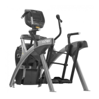
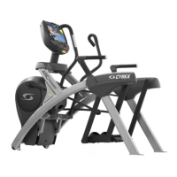
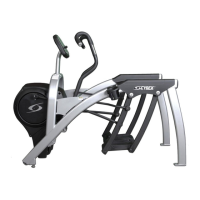
Related product manuals