8. Pin Assignment
Example:
⑤
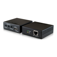
IR Receiver: This slot is where you connect the IR receiver cable, place the
IR eye in front of the display then use the existing remote to control the
input source equipment. The IR receiver has a frequency range from
30KHz to 50KHz.
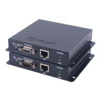
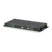
7.2 Rear Panel
CH-1106TX CH-1106RX
①
DDC input/output: Connect the DDC output transmitter to the DDC input
of
the receiver using a CAT6 cable.
②
Video input/output: Connect the video output of the transmitter to the
video input of the receiver using a CAT6 cable.
① ②