10
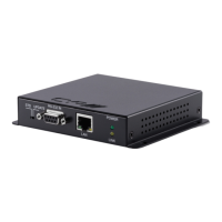
6.4 Front Panel of Receiver
1 2 3 4 5 6
POWER OPT. IN IR IN 1IR OUT 2
RS-232
TX RX
UPDATE
1
Power LED: This power LED will illuminate when receiving the power
from transmitter.
2
OPT. In: Connects with optical audio source as optical audio return
which allowing audio transmit to Transmitter.
3
IR IN 1: IR IN 1 considered as IR extender which to connect to
the supplied IR Extender cables for IR signal reception. Ensure
that remote being used is within the direct line-of-sight of the IR
Extender.
4
IR Out 2: IR Out 2 considered as IR BLASTER which connects to the
supplied IR Blaster cable for IR signal transmission. Place the IR
Blaster in direct line-of-sight of the equipment to be controlled.
5
RS-232: Connect to the device that is to be controlled (via RS232
terminal connects with D-Sub 9-pin cable) by RS-232 commands.
6
Update: When update the fi rmware, the switch shall arrange to left
side (just follow arrow direction on case) and arrange back when
completing update.
 Loading...