ROBOT.HEAD to TOE
Product User’s Manual - MDDS30
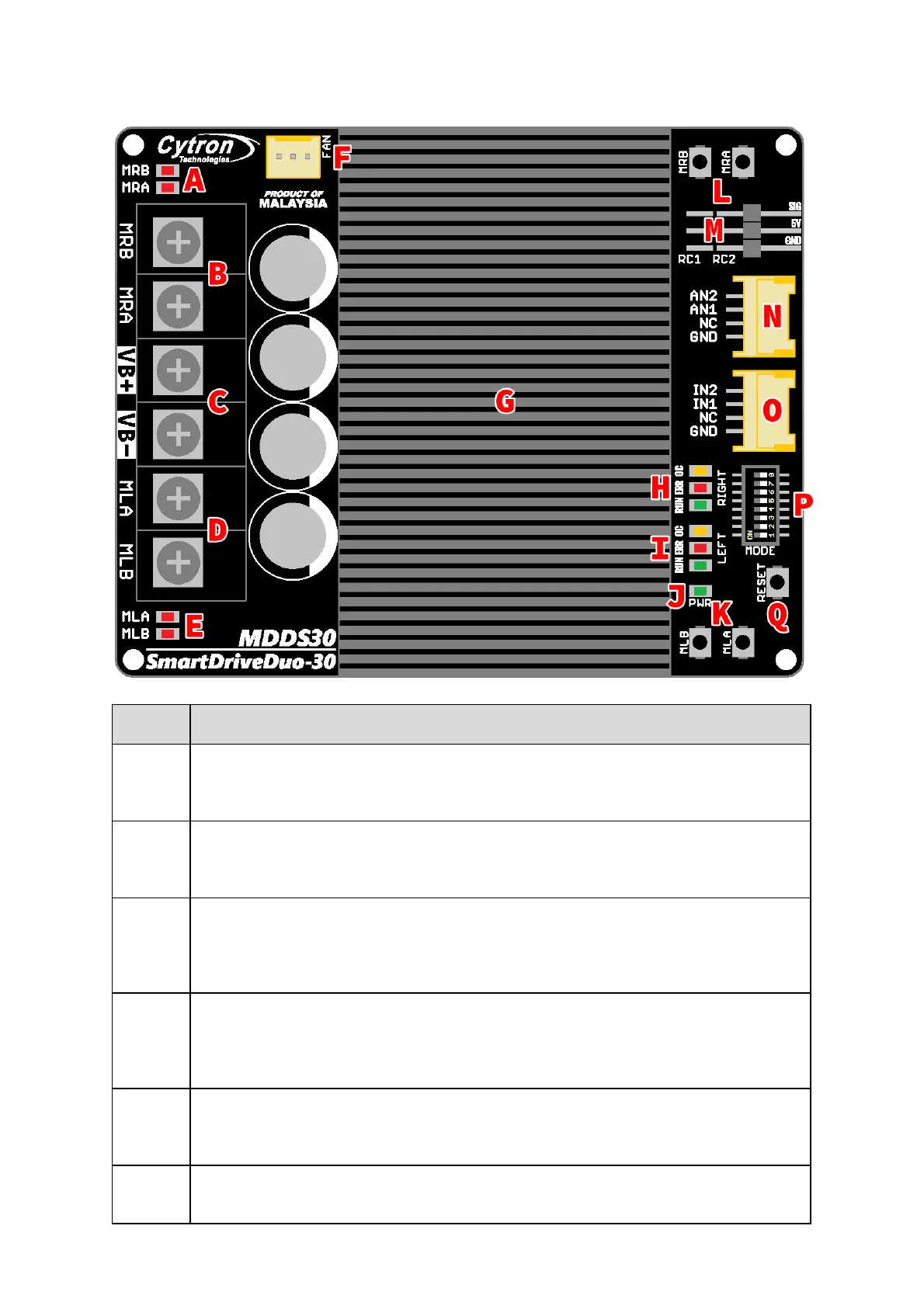
MOTOR RIGHT LED INDICATOR
Indicaon for current flow and direcon for motor RIGHT. If LED MRA turns on, means current
flows from output MRA to MRB. Vice versa.
MOTOR RIGHT TERMINAL BLOCK
Connect to motor RIGHT at your mobile robot. User can screw to lock the wire to the terminal
block. Please use wire with proper thickness to support the expected current.
POWER SUPPLY TERMINAL BLOCK
Connect to baery power source. User can screw to lock the wire to the terminal block. NO
POLARITY PROTECTION , please double check the connecon before power up. Please use wire
with proper thickness to support the expected current.
MOTOR LEFT TERMINAL BLOCK
Connect to motor LEFT at your mobile robot. User can screw to lock the wire to the terminal
block or solder the wire directly to the pad at the boom layer. Please use wire with proper
thickness to support the expected current.
MOTOR LEFT LED INDICATOR
Indicaon for current flow and direcon for motor LEFT. If LED MLA turns on, means current
flows from output MLA to MLB. Vice versa.
COOLING FAN CONNECTOR
Oponal cooling fan (not included) can be connected here and mounted at the boom PCB. Pin
Created by CytronTechnologiesSdnBhd – All Rights Reserved
Back to INDEX 6