ROBOT . HEAD to TOE
Product User’s Manual – MD30C
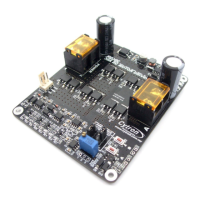
4. Internal PWM Potentiometer
Used to control the motor speed when PWM source is internal potentiometer.
5. External PWM Potentiometer Port
Connect to the external potentiometer (10K Ohm). Used to control the motor speed when
PWM source is external potentiometer.
6. Test Button A
When this button is pressed, current flows from output A to B and motor will turn CW (or
CCW depending on the connection). External switch can also be connected for the ease of
access.
7. Test Button B
When this button is pressed, current flows from output B to A and motor will turn CCW
(or CW depending on the connection). External switch can also be connected for the ease
of access.
8. Motor Terminal Block
Connect to motor. For high current application, please solder the wire directly to the pad
at bottom layer.
9. Red LED A.
Turns ON when the output B is low and output A is high. Indicates the current flows from
output A to B.
10. Red LED B
Turns ON when the output A is low and output B is high. Indicates the current flows from
output B to A.
11. Green Power LED
Turn on when the MD30C is powered up.
Created by Cytron Technologies Sdn. Bhd. – All Right Reserved 7