ROBOT . HEAD to TOE
Product User’s Manual –SN-E18-B03N1
4.2 Product Layout
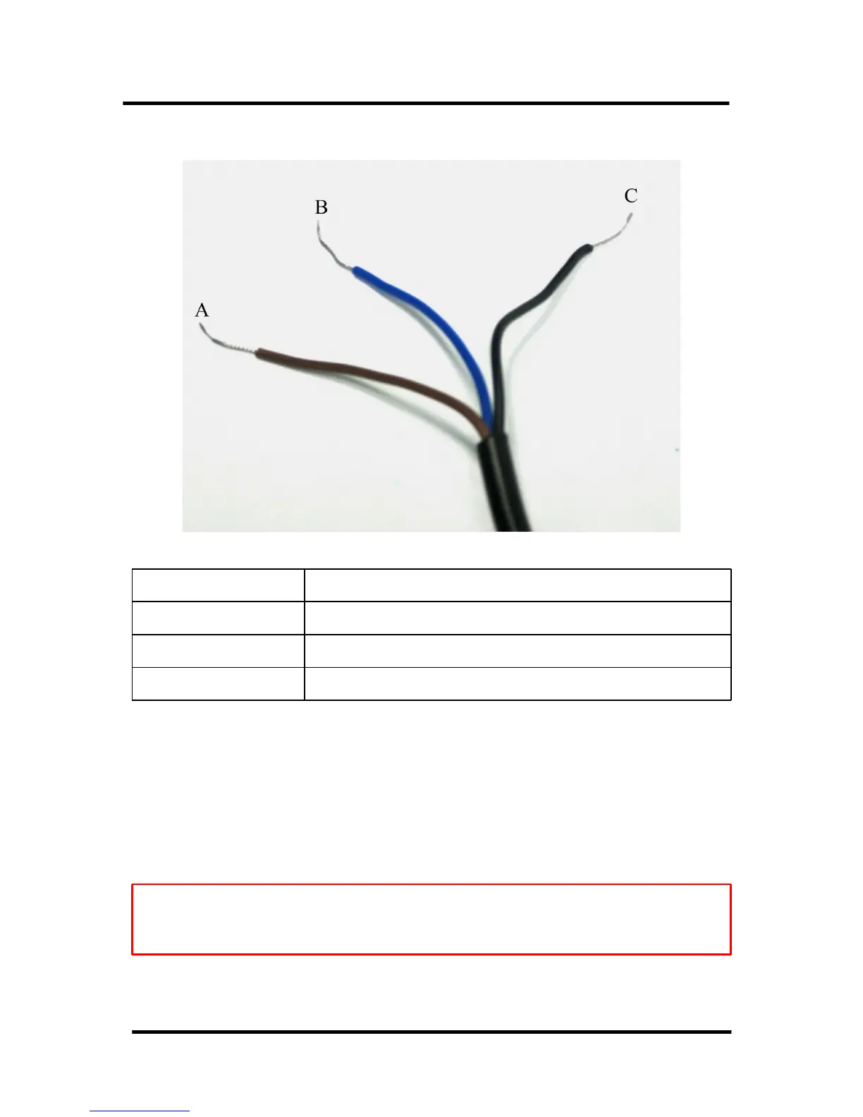
Label Function
A Connect VCC(+)
B Connect GND(-)
C Connect Output Signal (S)
A- User may supply 6V-36V to SN-E18-B03N1, the typical voltage is 12V.
B-User may connect the GND (-) of SN-E18-B03N1 to the Ground (0V) of he control board.
C-User may connect output signal to an I/O pin of microcontroller which set to INPUT mode.
The output signal of Digital Infrared Sensor is needed to be pull high as it is NPN output. The
module will output a HIGH if no object is detected and a LOW if an object is detected.
Note: Although the specification stated it is NPN output, we notice the sensor itself is
being pull-up internally. Causing the output pin is being pull up to power pin. So if 12V is
supply, you will get ~12V at output when no obstacle is detected.
Created by Cytron Technologies Sdn. Bhd. – All Rights Reserved 8