EasyManua.ls Logo

dacell DN520N - Page 48

Default Icon
53 pages
Print Icon
To Next Page IconTo Next Page
To Previous Page IconTo Previous Page
Loading...
PAGE 47 / 53
7. BCD Output (Option)
This “BCD interface” option card can be applied on PLC (Programmable Logic Controller), or Score
Board applications.
Each Input circuit is isolated with “Photo-Coupler”, from external devices electrically.
PIN NO.
SIGNAL
PIN NO.
SIGNAL
1
GROUND(GND)
26
HI : NET, LOW : Gross
2
1 × 10
0
27
NC
3
2 × 10
0
28
NC
4
4 × 10
0
29
NC
5
8 × 10
0
30
NC
6
1 × 10
1
31
EX INPUT3 (Part Number)
7
2 × 10
1
32
EX INPUT2 (Part Number)
8
4 × 10
1
33
NC
9
8 × 10
1
34
NC
10
1 × 10
2
35
NC
11
2 × 10
2
36
NC
12
4 × 10
2
37
NC
13
8 × 10
2
38
NC
14
1× 10
3
39
NC
15
2 × 10
3
40
NC
16
4 × 10
3
41
NC
17
8 × 10
3
42
Hi : Positive Polarity (+)
18
1 × 10
4
43
HI : Decimal Point 10¹
19
2 × 10
4
44
HI : Decimal Point 10²
20
4 × 10
4
45
HI : Decimal Point 10³
21
8 × 10
4
46
HI : OVER LOAD
22
1 × 10
5
47
Positive, Negative output (F-50)
23
2 × 10
5
48
EX INPUT1 (Part Number)
24
4 × 10
5
49
BUSY
25
8 × 10
5
50
EX INPUT0 (Part Number)
* F60 , 0 Positive output, 1 Negative output
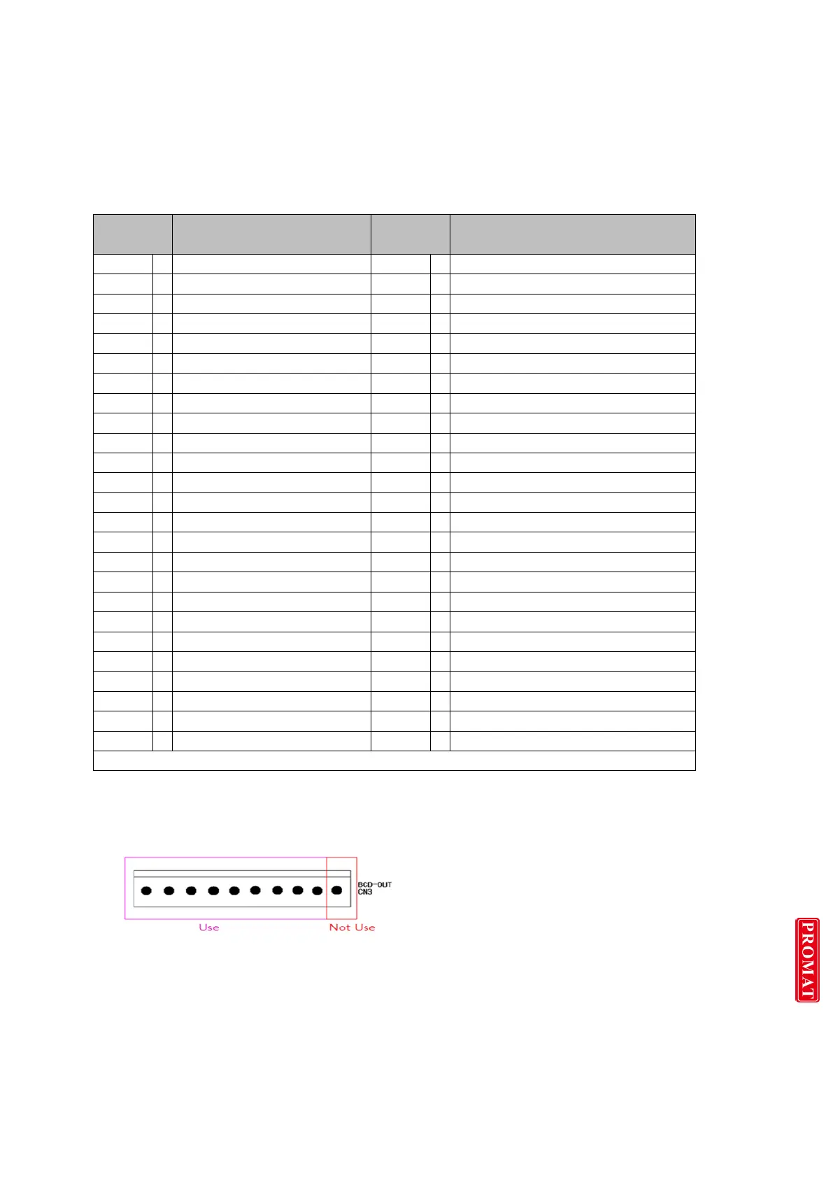
*** Please donot connect + Polarity at No.1PIN1. Only connect GND Polarity
The 9 Pin connector is connected at CN3 of main board.

Related product manuals