Do you have a question about the dacell DN501A and is the answer not in the manual?
Explains symbols indicating potential hazards and safety precautions.
Details symbols related to electrical safety and operation prohibition.
Outlines intellectual property rights and usage permissions for the manual.
Provides contact details for customer support and further information.
General overview of the DN501A model and its capabilities.
Lists important safety and operational precautions to prevent damage or injury.
Highlights key technical features and performance aspects of the weighing indicator.
Lists all items included in the product packaging.
Specifies technical parameters for analog signal input and conversion.
Details specifications for the digital display, status lamps, and keypads.
Provides overall technical specifications like power, dimensions, and weight.
Lists available optional interface and output cards for expanded functionality.
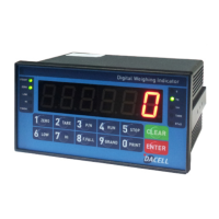
Describes the layout and components of the indicator's front control panel.
Details the connectors, ports, and switches located on the rear of the indicator.
Provides physical dimensions and required cut-out size for mounting.
Explains the formula for designing an accurate weighing system using load cells.
Process to adjust and balance the scale's weight readings.
Step-by-step guide for calibrating using known test weights.
Alternative calibration method without needing physical test weights.
Procedure for configuring various operational functions of the indicator.
Comprehensive catalog of all available functions and their setting ranges.
Details on connecting via RS-232C serial interface, including connection and data format.
Details on connecting via Current Loop serial interface for robust communication.
Details on connecting via RS-422 serial interface for enhanced noise immunity.
Explains the command structure for controlling the indicator via serial communication.
Details on the 0-10V analog voltage output option for external devices.
Details on the 4-20mA analog current output option for external devices.
Details on connecting a standard serial printer for printing data.
Provides examples of different serial print formats (single, continuous, sub-total, grand total).
Lists and explains various test modes for diagnosing indicator functions.
Troubleshooting specific errors related to load cell installation and connection.
Lists and explains common errors encountered during the calibration process.
| Brand | dacell |
|---|---|
| Model | DN501A |
| Category | Accessories |
| Language | English |