DACELL CO., LTD
http://www.dacell.com
TEL:+82-43-2602242, FAX : +82-43-2602245
2
Checks install place and connection prior to setting, caution the following
instruction.
* No power ON/OFF switches.
Cautions to operate from the voltage supply the moment.
* Input/output part are not isolated electrically. Use the specific cable to protect
indicator against over voltage and current and indicator get to the ground connection
* Setting lock mode for system and data protection
* Do not internal disjointing and adjustment voluntarily because the indicator is
composed of electron component and P.C.B circuit to sharp at the static electricity .
DACELL is not liability for mistake to use that change a property voluntarily, change
design, adjustment voluntarily, user carelessness cause defect.
1. Installation
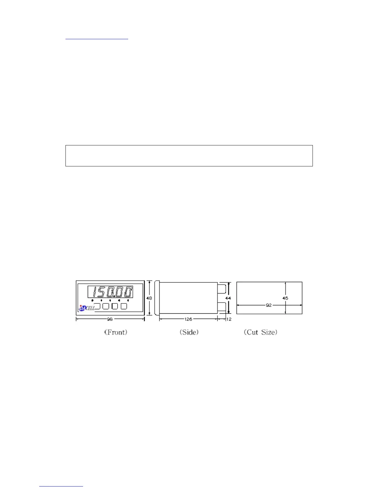
1) Product Spec.
- Spec : 96 ㎜×48 ㎜/3.78“ × 1.89"(1/8 DIN)
depth : 126 ㎜/4.96"
- SIZE : 92 ㎜(+1.0/-0) × 45 ㎜(+0.8/-0)
3.62“(+0.04/-0)× 1.77“(+0.03/-0)
* Mount the indicator using Bracket.
* Get a indicator into front of the panel and fixing guide push in a terminal direction
and volt fix.
* Thickness of mounting plane : 1 ㎜~8 ㎜
2) Install place
Install the indicator separately from switching device and relay, avoid
installation as follows.
* MC, Switching device, relay * Thyristor unit
* Motor * Dust, moisture, corrosion gas, heat line exist place.
* Operating temperature : 0 ~ 50 ℃
3) Power characteristics
* Install line filter if harmonic source and arc welder exist around.
* Separate sensor and control line from power line
 Loading...