DACELL CO., LTD
http://www.dacell.com
TEL:+82-43-2602242, FAX : +82-43-2602245
3
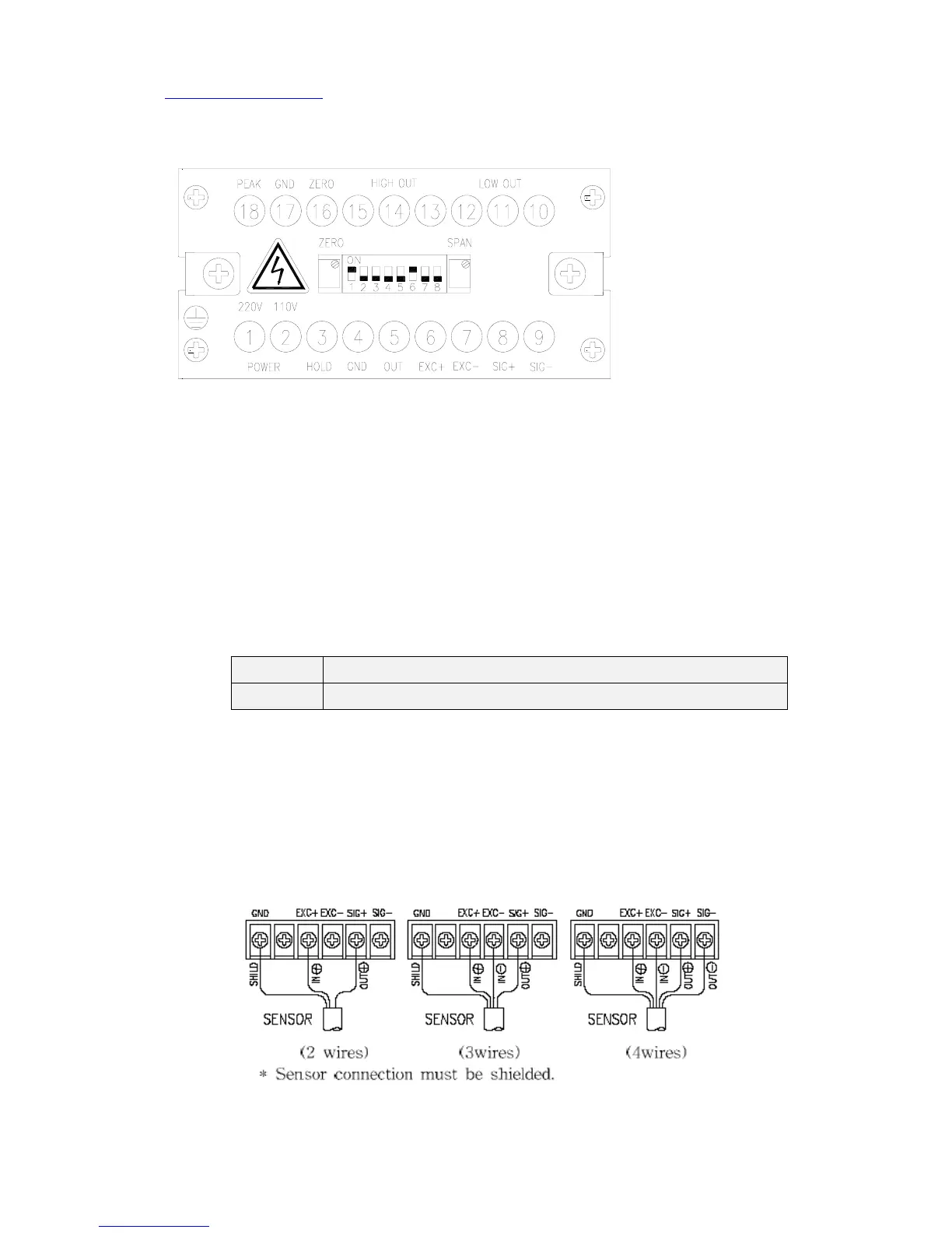
2. Connection and wiring
1) AC input : 1 and 2 ports, 110/ 220V (50Hz/60Hz).
Separate power cable from sensor cable.
Refer to 5-1).
2) HOLD : 3 and 4 ports.
short state : current display value holding
open state : current value display(normal operation mode)
3) ANALOG OUTPUT : 4 → -(GND), 5 → +
Analog output is as following voltage or current
DIP switch 5 on : voltage output.
DIP switch 5 off : current output.
ON Voltage Output ( 0-5V, 1-5V ,0-10V, 2-10V)
OFF Current Output ( 0-10 ㎃, 0-20 ㎃, 4-20 ㎃ )
Adjust zero point and maximum point of analog output using
zero and span VR
signal 0 : zero VR → 0V, signal max : span VR → 10V
zero range : -3V~ +3V, span : 10.5V
0~10V : Switch 5 off → current output mode (0 ~ 20 ㎃)
4) SENSOR connection port : 6,7,8,9 ports
Set the hardware and software as following conditions.
 Loading...