DACELL CO., LTD
http://www.dacell.com
TEL:+82-43-2602242, FAX : +82-43-2602245
8
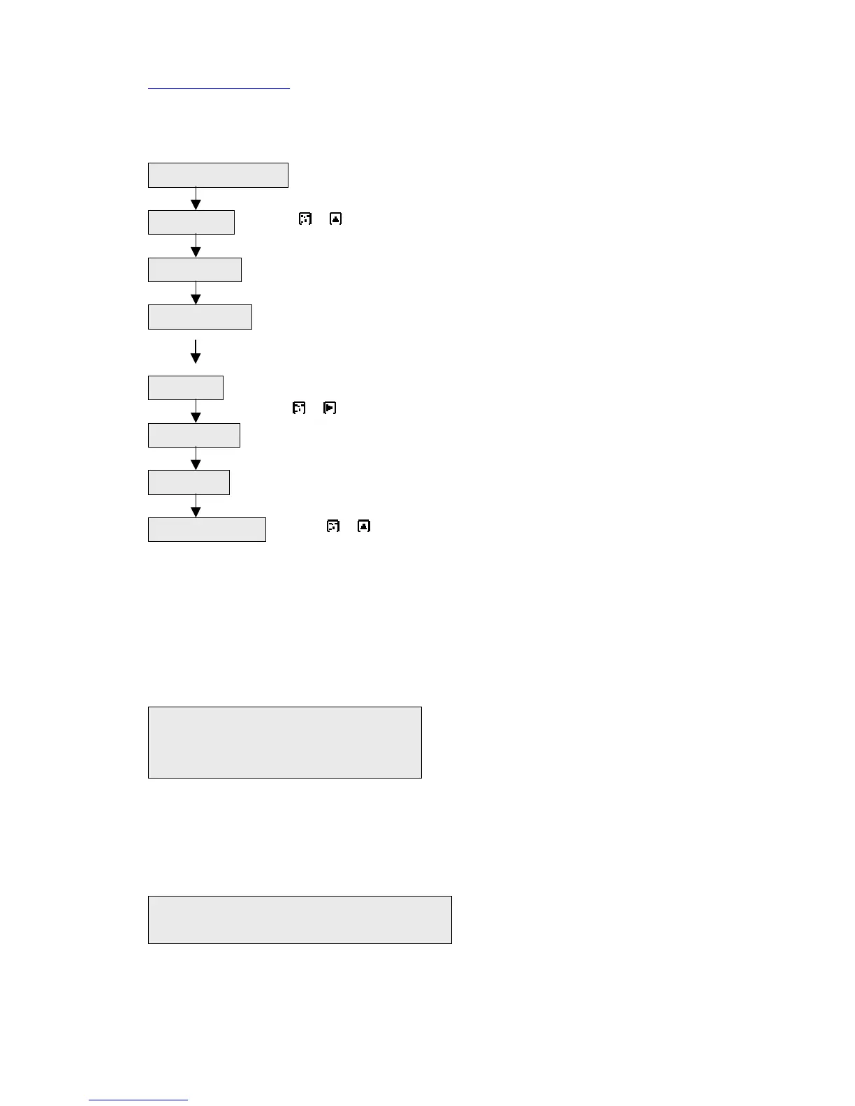
4. Operating flow chart
--Mount indicator to panel and make connection. (Check AC
POWER 110/220V)
-- Press + key(data protection unlock)
-- Set data(high, low, F.S, DP, CAL),refer to 6
--sensor output data ---DIP S/W 1, 2, 3, 4
analog output ---- DIP S/W 5
filter frequency ---- DIP S/W 6, 7, 8
-- Sensor : no load
Press + key (auto zero)
---Execute auto calibration.
---Check function(Relay output,analog output, reset, hold, peak).
--Press + key(data protection mode)
5. HARDWARE
1) Selection of AC input power
(1) Separate P.C.B from case.
(2) The following label is existed under power transformer
2) Transformation of SAMPLING TIME
15 times/sec (standard).
(1) The following label is existed on the P.C.B
Install and connection
Unlock mode
DATA Input
DIP S/W setting
Auto zero
AUTO CAL
Mode Check
Lock mode setting
① ② ③ ④ 110V : connect 1 and 2
110 220 110 connect 3 and 4
220V : connect 2 and 3
○ ○ ○ 15 times/sec : connect 1 and C
15 C 30 30 times/sec : connect 2 and C
 Loading...