DACELL CO., LTD
http://www.dacell.com
TEL:+82-43-2602242, FAX : +82-43-2602245
9
3) Setting of DIP switch
After connection, dip s/w must be set.
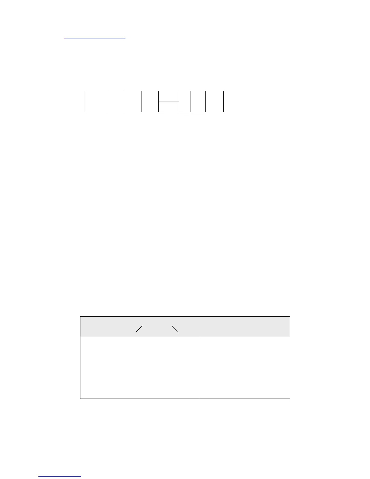
ON 1 2 3 4 5 6 7 8
1~4 S/W :One of 1,2,3 or 4 turn on according to sensor output value (mV/V)
5 S/W : Turn on or off according to analog output
6,7,8 S/W : Analog input filter frequency 6,7,8 turn off : 4 ㎑
6. SOFTWARE
1) CALIBRATION DATA
Set data as follows according to sensor output value.
Confirm calibration data after auto calibration execution.
1 mV/V range --- 0.700 ~ 1.249 mV/V
1.5 mV/V range --- 1.250 ~ 1.749 mV/V
2 mV/V range --- 1.750 ~ 2.499 mV/V
3 mV/V range --- 2.500 ~ 3.500 mV/V
2) Adjustment of display time and measurement data unit
(1) Press mode key, FS+DP LED turn on at the same time.
(2) 01.01 is displayed.
(3) Display time (set 1 times : fastest, set 15 times : slowest)
voltage
1 mV/V
1.5
mV/V
2
mV/V
3
mV/V
current
1Hz10Hz100Hz
0 1 . 0 1
Setting of displat time Setting of adjustment width
01 - After 1 times sampling, display
02 - After 2 times “
: :
: :
14 - After 14 times “
15 - After 15 times “
01 : display 1, 2, ……, 9
02 : display 2, 4, 6, 8, 0(even)
05 : display 5, 10, 15
10 : display 10.....90
20 : display 20, 40, 60, …
50 : display 50, 00
 Loading...