77
Part name & Treatment for each device
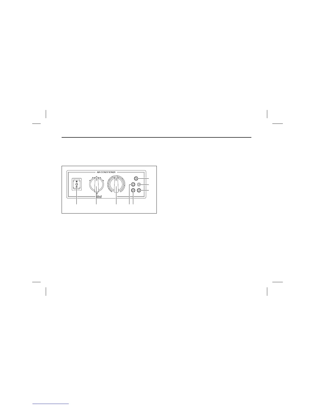
1. Control panel
1. Operation & Pre-heater switch
2. Blower air control switch
3. Indoor TEMP. setting switch
4. Power operation lamp
5. Oil buzzer lamp
6. COMP. Buzzer lamp
7. Battery charging lamp
8. Cold water buzzer lamp
2. Function of each switch
1) Operation & Pre-heater switch
The organization of switch is dumbuler switch as
2 stage, heat ON is using for pre-heating to glow
plug, start ON is using for engine operation of AIR
-CON.
(Do not use it for more than 10 sec. At pre-heater
& for more than 3 sec. at operating)
2) Blower air control switch
The switch is used at air control of AIR-CON blow-
er & engine stop as 5 stages.
1 OFF : at AIR-CON stop.
2 LOW : The air of AIR-CON blower is operated at
LOW.(60% of total air)
3 MID : The air of AIR-CON blower is operated at
MID.(80% of total air)
4 HIGH : The air of AIR-CON blower is operated
at HIGH.(100% of total air)
5 AUTO : Blower AIR-CON is controlled automati-
cally depending on INDOOR & SETTING
TEMP.(3 stage control of auto air)
 Loading...