53
1. SAFETY PRECAUTIONS
Before operating the generating set, read the generating set operation manual and this
generator manual and become familiar with it and the equipment. The following symbols are
used in the user manual or on the product:
SAFE AND EFFICIENT OPERATION CAN ONLY BE ACHIEVED IF THE EQUIPMENT IS
CORRECTLY OPERATED AND MAINTAINED.
Many accidents occur because of failure to follow fundamental rules and precautions.
ELECTRICAL SHOCK CAN CAUSE SEVERE PERSONAL INJURY OR DEATH.
• Ensure installation meets all applicable safety and lacal electrical codes. Have all installa-
tions performed by a qualied electrician.
• Do not operate the generator with protective covers, access covers or terminal box covers
removed.
• Disable eng ine start circuits before carrying out maintenance.
• Disable closing circuits and/or place warning notices on any circuit breakers normally used
for connection to the mains or other generators, to avoid accidental closure.
Observe all IMPORTANT, CAUTION, WARNING, AND DANGER notices, dened as:
IMPORTANT! Important, refers to hazard or unsafe method or practice which can result
in product damage or related equipment damage.
CAUTION! Caution, refers to hazard or unsafe method or practice which can result in
product damage or injury to personnel.
Warning! Warning refers to a hazard or unsafemethod or practice that can result
severe injury to personnel, possibly death.
Danger! Danger, refers to immediate hazards which will result in severe injury or
death to personnel.
Due to our policy of continuous improvement, details in th is manual which were correct at
time of printing, may now be due for amendment. Information included must herefore not be
regarded as binding.
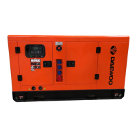
Photograph
The Front Cover photograph is representative only.
2. INTRODUCTION
2.1 INTRODUCTION
The generator is of brushless rotating eld design, available up to 660V at 50Hz or 60Hz. The
design, build and text procedures meet a range of British, European and international stan-
dards including, BS 5000, BS EN 60034 and ISO 60034, Where applicable. The generators are
tted with the PMG Pilot exciter system and an automatic voltage regulator (AVR). The MX 341
or the MX 321 can be tted.
2.2 SERIAL NUMBER LOCATION
Each generator has ns unique serial number stamped int. the upper section of the drive end
frame end-ring. Inside the term inal box two adhesive rectangular labels have been xed, each
carrying the generator's unique identity number. One label has been xed to the inside of the
terminal box sheet metal-work, and the second label xed to the main frame of the generator.
2.3 DESIGNATION
3. PRINCIPLE OPERATION
3.1 EXCITED-AVR CONTROLLED GENERATORS
The main stator provides power for excitation of the exciter eld via the SX440 AVR which is
the controlling device governing the level of excitation provided to the exciter eld. The AVR
responds to a voltage sensing signal derived from the main stator winding By controlling the
low power of the exciter eld, control of the high power requirement of the main eld is achie-
ved through the rectied output of the armature.
The SX440 AVR senses average voltage on two phases ensuring close regulation. In addition it
detects engine speed and provides voltage fall off with speed. Below a pre-selected speed
(Hz) setting, preventing over-excitation at low engine speeds and softening. The effect of load
switching to relieve burden on the engine.
4. APPLICATION OF THE GENERATOR
The generator is supplied as a component part for installation in a generating set. It is not,
therefore, practicable to t all the necessary warning/hazard labels during generator
manufacture. The additional labels required are packaged with this manual, together with a
drawing identifying their locations.(see below).
It is the responsibility of the generating set manufacturer to ensure that the correct labels are
tted, and are clearly visible.
 Loading...