
J
Jenny LeeAug 3, 2025
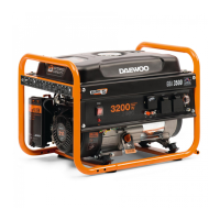
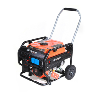
What to do if my Daewoo Portable Generator will not start?
- JJeffrey BennettAug 3, 2025
If your Daewoo Portable Generator won't start, several issues could be the cause. First, ensure there's enough fuel in the tank. If the fuel valve isn't on, switch it to the 'on' position. Check if the fuel bowl is blocked. Also, verify the engine oil level and add oil if it's low. Make sure the engine switch is in the 'on' position. Finally, the spark plug could be faulty, and may need cleaning or replacing.