Do you have a question about the Daewoo FRU-5711-FRS-U20DA Series and is the answer not in the manual?
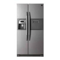
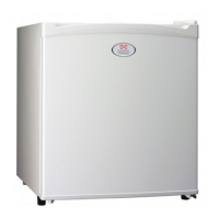
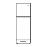
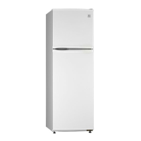
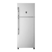
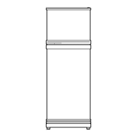
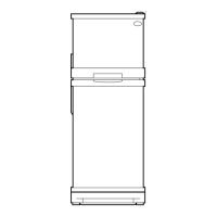
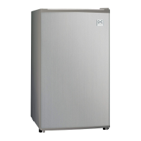
Provides dimensions for various refrigerator models.
Identifies internal components of the freezer and refrigerator compartments.
Details refrigerator specifications like volume, weight, and dimensions.
Explains the display panel and temperature control for FRS(N)-U20IA.
Describes the sequence of Pre-Cool, Heater Defrosting, Pause, and Fan-Delay.
Details the A/S Defrosting Mode sequence with specific steps.
Explains the control mechanism for the louver heater.
Details the control and function of buzzers and alarms.
Explains the control logic for interior lights based on door switches.
Explains the demonstration mode operation for FRS(N)-U20IA.
Explains the demonstration mode operation for FRS(N)-U20DA/EA/FA/GA.
Lists error codes and their corresponding LED displays for FRS(N)-U20IA.
Details causes and control methods for various sensor and system errors.
Lists error codes and their descriptions for FRS(N)-U20DA/EA/FA/GA.
Summarizes A/S functions and their activation methods for FRS(N)-U20IA.
Summarizes A/S functions and their activation methods for FRS(N)-U20DA/EA/FA/GA.
Describes backup functions for FRS(N)-U20DA/EA/FA/GA models.
Illustrates the step-by-step process of ice making.
Details the ice making and ice separating modes and their conditions.
Describes the ice separating mode timing and operation.
Explains the water supply mode process and checks.
Details how to check water supply status using sensors.
Explains the initial dispenser mode and selection icons.
Explains temperature control modes and display for Magic Cool Zone.
Shows timing charts for dispenser control (Crushed Ice, Cubed Ice, Water).
Provides power circuit diagrams for FRS(N)-U20IA and FRS(N)-U20DA/EA/FA/GA.
Explains F-sensor function, working points, resistance, and voltage.
Explains R-sensor function, working points, resistance, and voltage.
Explains D-sensor function, working points, and return point of defrost heater.
Shows the relay circuit diagram for FRS(N)-U20IA.
Shows the relay circuit diagram for FRS(N)-U20DA/EA/FA/GA.
Provides circuit diagrams for fan control for FRS(N)-U20IA and FRS(N)-U20DA/EA/FA/GA.
Shows the wiring diagram for FRS(N)-U20IA.
Shows the wiring diagram for FRS(N)-U20DA / EA / FA / GA.
Provides the circuit diagram for the main PCB.
Shows the location of components visible from the front.
Shows the location of internal components in freezer and refrigerator compartments.
Shows component locations within the evaporator section.
Shows component locations within the machine compartment.
Details disassembling and checking procedures for the hose ice maker tube.
Details disassembling and checking procedures for the bracket geared motor.
Details disassembling and checking procedures for the dispenser micro switch.
Details disassembling and checking procedures for the dispenser solenoid valve.
Identifies items on the Main PCB for FRS(N)-U20IA and their check points.
Identifies items on the Main PCB for FRS(N)-U20DA/EA/FA/GA and their check points.
Details disassembling and checking procedures for the ice maker.
Provides a flowchart for diagnosing start failures and power issues.
Flowchart for diagnosing freezing failures in the freezer compartment.
Step-by-step guide for removing freezer parts.
Shows specific components and their locations for removal.
Flowchart for diagnosing ice formation on the F-Louver.
Guides on diagnosing and fixing refrigerator light wire issues.
Flowchart for diagnosing refrigeration failures.
Guides on diagnosing and fixing refrigerator light wire issues.
Flowchart for diagnosing dew formation in the refrigerator compartment.
Flowchart for diagnosing excessive refrigeration in the vegetable case.
Flowchart for diagnosing compressor operation noise issues.
Flowchart for diagnosing refrigerant flow sounds.
Addresses hiss, sizzling, and shaking sounds from the evaporator.
Guides on fixing fan noise issues like loose mounting or touching.
Guides on fixing fan noise issues like loose mounting or touching.
Flowchart for diagnosing pipe noise issues.
Flowchart for diagnosing persistent door opening alarms.
Outlines the processes and tools for heavy cooling cycle repairs.
Lists precautions for using tools, refrigerant removal, and welding.
Details practical steps for refrigerant removal and nitrogen blowing welding.
Covers vacuum degassing and refrigerant charging procedures.
Provides safety regulations for heavy repair tasks like welding and pipe handling.
Guides on checking dimensions and finding a suitable installation place.
Provides instructions for removing freezer and refrigerator doors.
Details steps for replacing freezer and refrigerator doors.
Explains how to level the refrigerator and adjust doors for balance.
Provides instructions for installing the water line for the icemaker.
Details the installation procedure for the water line and filter box.
Continues water line installation steps and after-installation checks.
Lists compressor and capacitor specifications.
Shows different power cord shapes and part codes.
| Brand | Daewoo |
|---|---|
| Model | FRU-5711-FRS-U20DA Series |
| Category | Refrigerator |
| Language | English |