3
ZF INTARDER
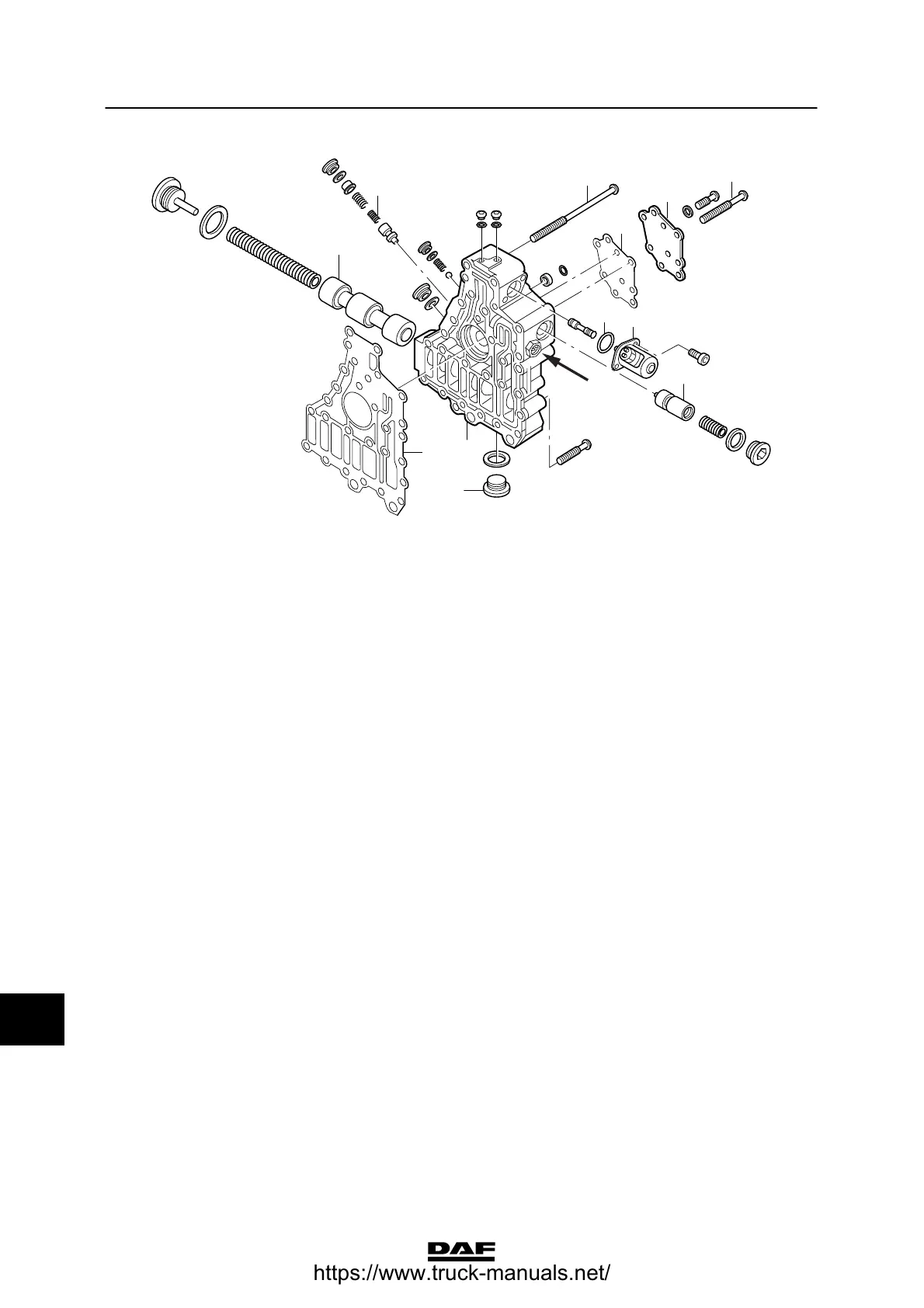
Removal and installation CF65/75/85 series
4-8
V300075
5
8
7
6
5
4
2
3
1
9
10
5
4. Remove the control unit (7) and the
gasket (8).
5. If necessary, remove and inspect the
plungers and springs (5). Avoid damaging
the plungers and plunger guides.
Note:
The sealed plunger (see arrow in
illustration) must not be removed; after
removal, the intarder must be set again on
the test bench.
Installing the hydraulic control unit
1. Fix the gasket (8) in the gearbox with as
many long studs as possible. The studs
also serve as guide pins to facilitate
mounting of the control unit.
2. Line up the end of the oil pump with the
output side of the stator.
3. Fit the control unit over the studs and be
sure to position the control unit carefully
against the housing to make sure that the
oil pump is in its place in the stator. Tighten
the attachment bolts to the specified torque.
See “Technical data”.
4. Install the heat exchanger.
12
ᓻ 200337
https://www.truck-manuals.net/