User’s Manual
2
2 Device Structure
Front Panel
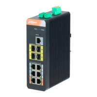
Front panel
Table 2-1 Description of front panel
SN Name
Description
1 Uplink1–Uplink2 10/100 Base-T, two 10/100 Mbps self-adaptive uplink ports.
2 PoE1–PoE4
10/100 Base-T, four 10/100 Mbps self-adaptive PoE power supply
ports.
3 PD Alive When PD Alive is on, IPC can be kept alive.
4 Extend Mode
In extend mode, data can be transmitted up to 250 m in CAT6 cable
with a bandwidth of 10 M.
5 Link/Act Single port Link status indicator.
6 PoE Single port PoE status indicator.
7 Act Data transmission status indicator of uplink port.
8 Link Link status indicator of uplink port.
9 PWR Power indicator.
Rear Panel
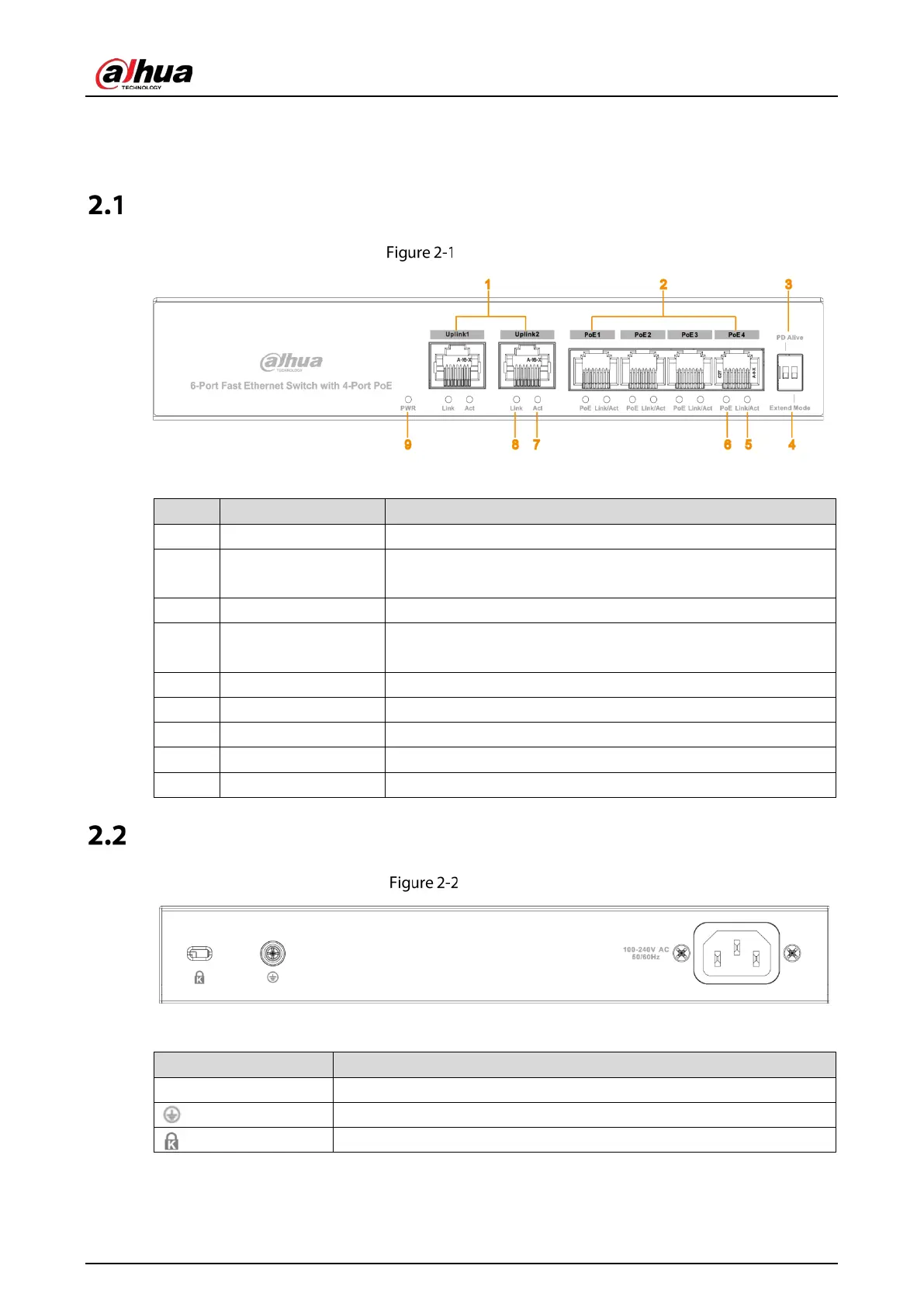
Rear panel
Table 2-2 Description of rear panel
Name
Description
PWR Power port. Supports 100V-240V AC power input.
GND.
The switch lock.
 Loading...