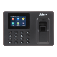
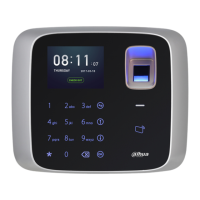
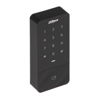
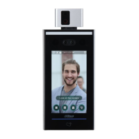
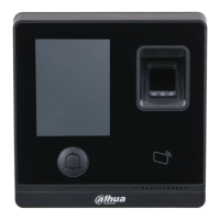
Wiegand /RS485 input/output.
Electric lock output, door sensor and exit button.
Power port and network port.
Table 2-2
2.5 Wiring Description
From left to right, terminal number is 1~8, as shown in Figure 2-7.
2.5.1 Wiring Description of Wiegand /RS485 Input/output
This device works as a card reader, and can connect a card reader.
It is an output device when it works as a card reader.
It is an input device when connecting a card reader.
Set input/output in “Main Menu > Connection > Wiegand”. Please refer to “3.9.3 Wiegand”
for details.
1 door only supports to connect one type of card reader, 485 or Wiegand.
In CON1, corresponding terminals are described in Table 2-3.
CON1
(Wieg
and
/RS45
8
input/o
utput)
CAT5E network cable, 485 connection
CAT5E network cable, Wiegand connection
Table 2-4
2.5.2 Wiring Description of Lock, Door Sensor and Exit Button
In CON2, corresponding terminals are described in Table 2-5. Please select a proper
connection depending on lock type, as shown in Figure 2-8, Figure 2-9 and Figure 2-10. Door
contact and exit button connection is shown in Figure 2-11.
 Loading...
