INTAKE
SYSTEM
-
,-C4
SURGE
TANK
f'
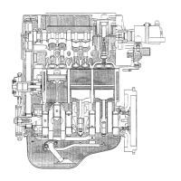
COMPONENTS
OF
SURGE
TANK
[CB-61 Engine]
Fig.
1 1-8
WM-11009
INSPECTION
1.
Check to see
if
the surge tank exhibits any sign of cracks
or damage.
2.
Disconnect the relief valve hose and blow your breath into
the surge tank. There should be no air continuity.
3.
Turbocharger Indicator Lamp
Inspection
Engine switch turned
ON
i
Apply positive pressure of
0.15
kg/cm2
(2.1
psi) to
vacuum
switch.
1
Turbo indicator lamp should go on.
0
Clip
@
Hose
@I
Hose
@
Nut
@
Bracket
@
Surge tank
I
I
Fig.
11
-9
WM-11~10
I
Vacuum switch
I
I
I
Fig.
11-10
WM-11011
 Loading...