5 Piping installation
Installation manual
16
2MXM-A, 3MXM-A, 4MXM-A, 5MXM-A
R32 Split series
3P600450-6R – 2022.05
Outdoor unit Total indoor unit capacity
class
4MXM80 ≤14.5kW
5MXM90 ≤15.6kW
Port Class Reducer
2MXM68
A (Ø9.5mm) 15, 20, 25, 35, (42)
(a)
—
B (Ø12.7mm) 15, 20, 25, 35, (42)
(a)
2+4
42, 50, 60 —
3MXM40
A (Ø9.5mm) 15, 20, 25, 35 —
B + C (Ø12.7mm) 15, 20, 25, 35 2+4
3MXM52
A (Ø9.5mm) 15, 20, 25, 35, (42)
(a)
—
B + C (Ø12.7mm) 15, 20, 25, 35 2+4
42, 50 —
3MXM68
A (Ø9.5mm) 15, 20, 25, 35, (42)
(a)
—
B + C (Ø12.7mm) 15, 20, 25, 35, 42 2+4
50, 60 —
4MXM68
A + B (Ø9.5mm) 15, 20, 25, 35, (42)
(a)
—
C + D (Ø12.7mm) 15, 20, 25, 35, (42)
(a)
2+4
42, 50, 60 —
4MXM80
A (Ø9.5mm) 15, 20, 25, 35, (42)
(a)
—
B (Ø12.7mm) 15, 20, 25, 35, (42)
(a)
2+4
42, 50, 60 —
C + D (Ø15.9mm) 15, 20, 25, 35, (42)
(a)
5+6
42, 50, 60 1+3
71 —
5MXM90
A + B (Ø9.5mm) 15, 20, 25, 35, (42)
(a)
—
C (Ø12.7mm) 15, 20, 25, 35, (42)
(a)
2+4
42, 50, 60 —
D + E (Ø15.9mm) 15, 20, 25, 35, (42)
(a)
5+6
42, 50, 60 1+3
71 —
(a)
Only in case of connection with FTXM42R.
Reducer type Connection
1 Ø15.9mm → Ø12.7mm
2 Ø12.7mm → Ø9.5mm
3 Ø15.9mm → Ø12.7mm
4 Ø12.7mm → Ø9.5mm
5 Ø15.9mm → Ø9.5mm
6 Ø15.9mm → Ø9.5mm
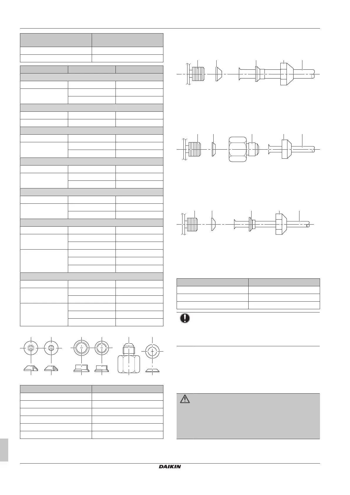
Connection examples:
▪ Connecting a Ø12.7mm pipe to a Ø15.9mm gas pipe connection
port
a Outdoor unit connection port
b Reducer no. 1
c Reducer no. 3
d Flare nut for Ø15.9mm
e Inter-unit piping
▪ Connecting a Ø9.5mm pipe to a Ø15.9mm gas pipe connection
port
a Outdoor unit connection port
b Reducer no. 6
c Reducer no. 5
d Flare nut for Ø9.5mm
e Inter-unit piping
▪ Connecting a Ø9.5mm pipe to a Ø12.7mm gas pipe connection
port
a Outdoor unit connection port
b Reducer no. 2
c Reducer no. 4
d Flare nut for Ø12.7mm
e Inter-unit piping
Coat the threaded connection port of the outdoor unit where the flare
nut comes in with refrigeration oil.
Flare nut for (mm) Tightening torque (N•m)
Ø9.5 33~39
Ø12.7 50~60
Ø15.9 62~75
NOTICE
Use an appropriate wrench to avoid damaging the
connection thread by overtightening the flare nut. Be
careful NOT to overtighten the nut, or the smaller pipe may
be damaged (about 2/3-1× the normal torque).
5.2.2 To connect the refrigerant piping to the
outdoor unit
▪ Piping length. Keep field piping as short as possible.
▪ Piping protection. Protect the field piping against physical
damage.
WARNING
Connect the refrigerant piping securely before running the
compressor. If the refrigerant piping is NOT connected and
the stop valve is open when the compressor is run, air will
be sucked in. This will cause abnormal pressure in the
refrigeration cycle, which may result in equipment damage
and even injury.
1 Connect the liquid refrigerant connection from the indoor unit to
the liquid stop valve of the outdoor unit.
 Loading...