Do you have a question about the Daikin CDX35HAV1NB and is the answer not in the manual?
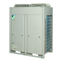
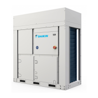
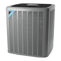
Details technical specifications for outdoor units, including capacity, power, dimensions, and refrigerant.
Details technical specifications for general indoor units, covering various types and capacities.
Details wiring diagrams and connector names for the Branch Provider Unit BPMK928B42 and B43.
Wiring diagrams and connector names for various outdoor unit models, including RMK, RMX, and RMK series.
Wiring diagrams and connector names for FTK, FTX, FTXD, and FVX series indoor units.
Wiring diagrams and connector names for FTK, FTKD, FTX, and FTXD series indoor units.
Wiring diagrams and connector names for CDX and CDK series indoor units.
Wiring diagrams and connector names for FLK and FLX series indoor units.
Wiring diagrams and connector names for FHYC series indoor units.
Wiring diagrams and connector names for FDYM series indoor units.
Explains key functions of split type indoor units, focusing on airflow and louvre control.
Explains the refrigerant system and the function of key components within the outdoor unit.
Details major functional parts of the outdoor unit, explaining their roles in the system.
Lists and describes protective devices, thermistors, and sensors used in the system.
Details protection devices specific to the outdoor unit to prevent damage and ensure safety.
Details protection devices specific to the BP unit to prevent damage and ensure safety.
Provides an overview of the system's control logic and how different components interact.
Explains the different operating modes and how the system configures them.
Explains how the initial operating frequency is determined for compressor reliability and optimization.
Explains how the system controls capacity, focusing on motorized valve operation for cooling.
Details the peak cut control function to regulate compressor frequency and prevent high pressure rise.
Explains how the system prevents indoor heat exchanger freezing by regulating compressor capacity.
Explains how discharge pipe temperature is controlled to regulate output frequency and prevent pressure rise.
Details input current control mechanisms to regulate operating frequency and prevent electrical part overheating.
Details functions for cooling electric parts and controlling fin temperature to prevent overheating.
Details the PI control mechanism for regulating command frequency based on ∆D signals.
Details the compressor protection control for ensuring oil level and dilution at startup.
Explains how fan rotation speed is controlled to prevent abnormal operation and ensure compressor reliability.
Outlines the operation of motorized valves (EVL, EVG, EVP) for system control and distribution.
Explains the subcooling control of the outdoor heat exchanger for efficient cooling.
Details BP unit motorized valve control for outdoor unit safety and optimum system performance.
Explains gas pipe isothermal control to ensure appropriate refrigerant distribution in cooling mode.
Details SH control for refrigerant distribution in cooling mode by adjusting motorized valves.
Explains the features and operation of the wireless remote controller.
Addresses troubleshooting for outdoor units that run but do not provide cooling or heating.
Explains how to interpret the 7-segment display on the outdoor unit's PC board for error codes.
Explains how to open the electrical box and remove the PCB mount for access.
Provides instructions for safely removing motorized valves from the unit.
Details the procedure for removing thermistors, noting factory-installed ones are not replaceable.
Explains how to remove the outer panels of the outdoor unit for access to internal components.
Details the process of removing the PCB and electrical box, including safety warnings.
Provides instructions for removing propeller fans and their motors from the outdoor unit.
Details the procedure for removing thermistors from the outdoor unit.
Explains how to remove motorized valves and associated components from the outdoor unit.
Provides instructions for safely removing the compressor from the outdoor unit.
Details the procedure for removing the 4-way valve assembly from the outdoor unit.
Directs users to a table for indoor unit removal procedures based on model number.
Details the installation procedures and service space requirements for the outdoor unit.
Provides installation procedures and restrictions for the BP unit.
Details electric wiring connection precautions for the outdoor unit, including safety measures.
Explains BP unit connection priority and wiring procedures.
Describes how to set the rotary switches on the outdoor unit for proper system configuration.