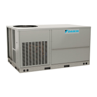
Do you have a question about the Daikin DCH090 Series and is the answer not in the manual?
Refrigerants are heavier than air; avoid enclosed spaces and frostbite.
Guidelines for selecting the proper location for unit installation.
High voltage warning and instructions for electrical connections.
Avoid personal injury or death due to electrical shock; do not tamper with factory wiring.
Instructions for connecting 24V thermostat and control wiring.
Procedures for unit startup, adjustments, and essential checks.
Disconnect all power before servicing or installing to avoid shock.
Disconnect power and padlock unit before servicing fans.
Step-by-step procedure for checking unit operation.
Step-by-step procedure for checking unit operation in cooling mode.
Explanation of defrost cycle initiation and termination.
Final checks before owner instruction, including air balance and leaks.
Routine maintenance items to be performed at regular intervals.
Troubleshooting chart for common cooling system complaints and remedies.
Procedure for measuring and verifying unit supply voltage and imbalance.
Testing the loss of charge protector for continuity and proper operation.
Checking the high pressure control for proper cutout and reset points.
Testing the low pressure control for correct cutout and reset pressures.
Checking compressor windings for continuity and ground faults.
Testing compressor windings for continuity.
Testing compressor windings for ground faults.
Testing compressor operation with capacitors and correct wiring.
Troubleshooting stuck or inoperative reversing valves.
Checking defrost control sequencing and relay operation.
Checking the temperature setpoints for defrost thermostat contacts.
General troubleshooting for heat pump heating cycle issues.
Common causes for poor heat pump performance during heating cycles.
Effects of an undercharged system on heating cycle performance.
Troubleshooting causes for reversing valve malfunction.
Proper procedures for repairing refrigeration systems, including brazing.
Procedures for leak testing refrigeration systems using nitrogen.
Procedure for evacuating the system to remove air and moisture.
Procedure for charging the system with the correct amount of refrigerant.
Diagnosing compressor inefficiency due to valve or scroll flank damage.
Procedure and table for checking system superheat.
Indications of overcharge and procedures to reduce refrigerant.
Identifying and removing non-condensables from the system.
Diagnosing compressor burnout and cleaning the system.
Wiring diagram for DCC090-150XXX6BXXX** unit models.
| Series | DCH090 |
|---|---|
| Category | Heat Pump |
| Heating Capacity | 9.0 kW |
| Refrigerant | R410A |
| Noise Level (Outdoor Unit) | 52 dB(A) |
| Weight (Outdoor Unit) | 48 kg |
| Power Supply | 220-240V, 50Hz |


 Loading...