D-EIMWC00804-14EN Centrifugal Chillers 35
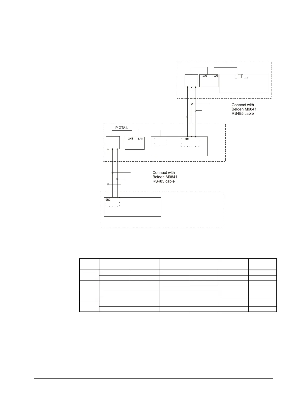
Figure 16, Communication Wiring
PIGTAIL
485
OPDR
C
A
B
SHIELD
UNIT CONTROL
J11 PORT
Chiller B
485
OPDR
C
BLU/WHT
WHT/BLU
SHIELD
B
A
UCM
J10
PORT
Chiller C
(+)
(-)
J11 Port
P
P
P
NOTE: A fourth chiller, Chiller D would be connected to chiller C same as chiller C to chiller B.
Table 11, Address DIP Switch Settings for Controllers Using pLAN.
Chiller
Comp 1
Comp 2
Unit
Reserved
Operator
Reserved
A
1 2 5 6 7 8
B
9 10 13 14 15 16
C
100010 010010 101010 011010 111010 000110
D
100110 010110 101110 011110 111110 000001
NOTES:
1. Up to four single or dual compressors can be interconnected.
2. The Operator Interface Touch Screen (OITS) setting is not a DIP switch setting. The OITS
address is selected by selecting the ‘service’ set screen. Then, with the Technician level
password active, select the ‘pLAN Comm’ button. Buttons A(7), B(15), C(23), D(31) will
appear in the middle of the screen, then select the letter for the OITS address for the chiller
that it is on. Then close the screen. Note that A is the default setting from the factory.
3. Six Binary Switches: Up is ‘On’, indicated by ‘1’. Down is ‘Off’, indicated by ‘0’.
 Loading...