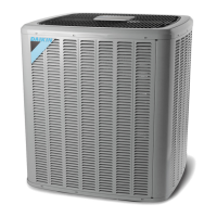
Do you have a question about the Daikin DZ18VC and is the answer not in the manual?
Provides safety information and contact details for consumers and servicers.
Outlines essential safety guidelines for handling refrigerants.
Discusses EPA regulations regarding refrigerant introduction and disposal.
Lists critical precautions to prevent explosion and injury.
Explains the model number coding system for units.
Details heater kit installation and valid switch settings.
Provides crucial safety warnings for handling capacitors.
High voltage warning before servicing or installing.
Step-by-step guide for removing and installing the electrical board.
Describes the operation of the condensing unit.
Explains the principles of the refrigeration cycle in cooling.
Describes the heating cycle operation.
Explains the defrost cycle control and operation.
Details how to enable, disable, and adjust BOOST MODE.
Explains thermostat settings for dehumidification.
Illustrates the cooling cycle with components and sensors.
Lists possible causes and their relation to heating issues.
Lists possible causes and their relation to cooling issues.
Critical safety warnings for electrical work during troubleshooting.
Procedure for checking unit supply voltage.
Steps for inspecting wiring for damage or loose connections.
How to check thermostat and its wiring.
Procedure for running the system start-up test.
Steps to set the thermostat to charge mode.
Guide to setting maximum compressor speed via thermostat.
Procedure to adjust indoor airflow trim.
Steps to force a defrost cycle using the thermostat.
Procedure to set the thermostat for pump down operation.
Safety warnings and procedures for checking the compressor.
Procedures for leak testing refrigeration systems.
Instructions for charging the refrigeration system.
Explains how to check and adjust subcooling.
General troubleshooting for the indoor unit.
Precautions for preventing ESD damage to components.
Lists diagnostic codes and their descriptions.
Troubleshooting the ComfortNet system communication network.
Table of thermistor resistance vs. temperature data.
R-410A pressure vs. temperature chart.
Required liquid line temperature for subcooling.
Wiring diagram for the indoor unit PCB.
| Type | Split System Heat Pump |
|---|---|
| SEER Rating | Up to 18 |
| HSPF Rating | Up to 10 |
| Refrigerant | R-410A |
| Stages | Variable |
| Compressor Type | Variable-Speed |


 Loading...