Do you have a question about the Daikin ERQ Series and is the answer not in the manual?
Details the safety cautions to be observed before conducting repair work.
Provides specific warnings and cautions for repair procedures to prevent electrical shock and injury.
Highlights important safety considerations and practices to follow after completing repair work.
Outlines essential checks to perform after repair to ensure proper and safe operation.
Explains the meaning of icons used throughout the manual to convey specific information.
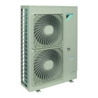
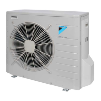
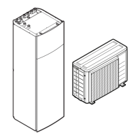
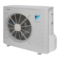
Details the model names for outdoor units, control boxes, and expansion valve kits.
Provides a comprehensive table detailing compatible combinations of outdoor units, control boxes, and expansion valve kits.
Lists the technical specifications for the outdoor units, including capacity, dimensions, and electrical data.
Details the refrigerant circuit diagrams for ERQ 125, 200, and 250 models.
Illustrates the layout of functional parts within the ERQ 125, 200, and 250 outdoor units.
Lists and defines symbols, operation modes, and general functions.
Details normal operation, compressor PI control, and fan control mechanisms.
Explains startup, oil return, defrosting, pump-down, standby, and stopping operations.
Details high/low pressure, discharge pipe, inverter, and compressor overload protection.
Covers emergency operation, demand operation, and heating prohibition.
Provides an overview of thermostat sensor, hot start, freeze prevention, and low outdoor air temp protection.
Details System A (PAIR) and System B (MULTI) with their control boxes.
Explains different control types: W, X, Y, Z and their characteristics.
Provides wiring diagrams for D-box and F-box, and connection tables.
Highlights important considerations for installation and operation.
Provides installation and operation manual for System A control boxes.
Covers accessories, parts, site selection, piping, electrical, thermistor, and test operation.
Details pre-operation checks, signals, troubleshooting, maintenance, and disposal.
Details piping limits, connections, material selection, and brazing cautions.
Describes mechanical installation and brazing work for the valve kit.
Details mechanical installation, wiring work, and precautions for the control box.
Explains the location and installation of refrigerant and air thermistors.
Shows the sequence of steps for installing the unit.
Details checks before power on, power on procedure, and air/vacuum drying.
Covers procedures for adding refrigerant and performing system check operations.
Details steps for performing the test run and post-test checks.
Describes initial power-on sequences and operations after unit addition or board changes.
Illustrates the components and layout of the outdoor unit's PC board.
Explains how to perform field settings using wired and simplified remote controllers.
Provides a summary of available field settings and their parameters.
Details system settings, control types, fan control, hot start, and thermostat control.
Details target refrigerant temperature settings for W- and X-controls.
Lists and explains setting items configurable from the outdoor unit.
Explains settings made via pushbutton switches on the PC board.
Details settings for low noise operation and demand operation.
Details procedures for setting refrigerant recovery and vacuuming modes.
Provides a detailed breakdown of check operation steps and LED indicators.
| Brand | Daikin |
|---|---|
| Model | ERQ Series |
| Category | Air Conditioner |
| Language | English |