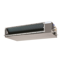
What to do if Daikin FBQ50D2VEB Air Conditioner detects multiple master units?
- DDr. Eric Torres MDAug 8, 2025
If your Daikin Air Conditioner detects multiple master units, connect the remote controller to only one indoor unit.
What to do if Daikin FBQ50D2VEB Air Conditioner detects multiple master units?
If your Daikin Air Conditioner detects multiple master units, connect the remote controller to only one indoor unit.
What to do if Daikin FBQ50D2VEB Air Conditioner has gas shortage due to clogging in refrigerant piping?
If you suspect clogging in the refrigerant piping system of your Daikin Air Conditioner, check for a failure to open the stop valve and any clogging within the refrigerant system.
What does excess indoor units connected error mean on Daikin FBQ50D2VEB Air Conditioner?
This error will be displayed if five or more indoor units are connected to your Daikin Air Conditioner.
Why does my Daikin Heat Pump emit an odor?
If your Daikin Heat Pump emits an odor, it's likely due to room smells and cigarette odors that have accumulated inside the indoor unit. To resolve this, the inside of the indoor unit must be cleaned.
Records changes and updates across different versions of the manual.
Crucial safety guidelines for handling equipment and performing repairs.
Explanation of icons used throughout the manual to convey specific information.
Introduction from the Daikin After Sales Service Division.
Specific safety measures for personnel performing maintenance or repairs.
Safety guidelines aimed at end-users for proper and safe operation.
Lists and categorizes the various indoor and outdoor unit model names.
Provides visual representations of the different outdoor unit models.
Defines the operational temperature limits for cooling and heating.
Details on the functions, operation, and settings of wired remote controllers.
Procedure for setting one remote controller as MAIN and another as SUB.
Procedure for setting group numbers for centralized control operations.
Overview of wireless remote controllers, applicable models, and their functions.
Configuration for setting receiver and remote controller addresses for wireless systems.
Describes the role and function of key components and thermistors in the system.
Visualizes the operational sequences for cooling/dry and heating modes.
Provides detailed explanations of various operational functions and controls.
Procedures and precautions for conducting initial operational tests after installation.
Instructions for configuring unit settings using the remote controller interface.
Mapping of settings and their corresponding codes for indoor units.
Configuration options to reduce the operational sound of the outdoor unit.
Adjusting settings for optimal performance in low humidity environments.
Procedures for adjusting settings directly on the outdoor unit's PCB.
Guidelines for performing routine maintenance checks on the air conditioning system.
Troubleshooting guide based on observed symptoms of system malfunction.
Diagnostic steps when the air conditioning unit fails to power on or operate.
Troubleshooting steps when the indoor fan runs but the compressor does not.
Diagnosing issues where the unit starts and then stops operation prematurely.
Methods for diagnosing faults using the remote controller's self-diagnosis features.
List and explanation of error codes displayed by the remote controller.
Schematic diagrams illustrating the refrigerant piping layout for the RZQG-L9V1 model.
Electrical wiring diagrams for the outdoor unit of various RZQG models.
Table detailing the thermodynamic properties of the R-410A refrigerant.
Instructions for safely removing and reinstalling the electrical switchbox.
| Brand | Daikin |
|---|---|
| Model | FBQ50D2VEB |
| Category | Air Conditioner |
| Language | English |


