EasyManua.ls Logo

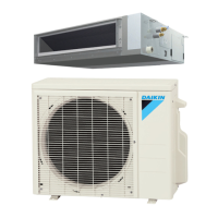
Daikin FDMQ12RVJU User Manual

Daikin FDMQ12RVJU
152 pages
To Next Page IconTo Next Page
Page #1 background imageLoading...
Page #1 background image
Service
Manual
Inverter Pair
Duct Connected Type
FDMQ-R Series
SiUS071735EB
[Applied Models]
Inverter Pair : Heat Pump

Table of Contents

Other manuals for Daikin FDMQ12RVJU

Questions and Answers:

Daikin FDMQ12RVJU Specifications

General IconGeneral
CategoryAir Conditioner
Cooling Capacity3.5 kW
Heating Capacity4.0 kW
RefrigerantR32
Power Supply50Hz
Noise Level (Outdoor Unit)50 dB
Indoor Unit Dimensions (WxHxD)800 x 295 x 200 mm

Summary

Part 1 List of Functions

1. Functions Overview

Provides a comprehensive list of all available operational functions for the unit.

Part 2 Specifications

1. Model Specifications

Details technical specifications including capacity, dimensions, power, and materials.

Part 3 Printed Circuit Board Wiring Diagrams

1. Indoor Unit Wiring Diagram

Illustrates the internal wiring and component connections for the indoor unit.

4. Outdoor Unit Wiring Diagram

Shows the internal wiring and component connections for the outdoor unit.

Part 4 Functions and Control

1. Main Functions

Details the primary operational modes and features of the air conditioning system.

2. Control Specification

Explains the system's control logic, modes, and operational parameters.

Part 5 Remote Controller

1. Wired Remote Controller

Operation and features of the wired remote controller unit.

2. Wireless Remote Controller

Operation and features of the wireless remote controller unit.

Part 6 Service Diagnosis

1. General Problem Symptoms

Identifies common symptoms and initial troubleshooting steps for system issues.

4. Troubleshooting Common Errors

Provides detailed troubleshooting guides for specific error codes and malfunctions.

Part 7 Trial Operation and Field Settings

1. Pump Down Operation

Procedure for safely removing refrigerant before relocating or disposing of the unit.

3. Trial Operation

Guidelines for conducting operational tests after installation and setup.

4. Field Settings Configuration

Instructions for adjusting unit settings based on installation environment and accessories.

Part 8 Appendix

1. Piping Diagrams

Visual representation of refrigerant and drain piping configurations for indoor and outdoor units.

2. Wiring Diagrams

Schematics detailing electrical connections between indoor, outdoor, and control units.

1. Safety Cautions

1.1 Worker Safety Warnings

Essential safety precautions for technicians during repair and maintenance operations.

1.2 User Safety Warnings

Important safety guidelines for end-users to prevent accidents and ensure proper operation.

2. Icons Used

Part 1 List of Functions

1. Functions Overview

Provides a comprehensive list of all available operational functions for the unit.

Part 2 Specifications

1. Model Specifications

Details technical specifications including capacity, dimensions, power, and materials.

Part 3 Printed Circuit Board Connector Wiring Diagram

1. Indoor Unit Wiring Diagram

Illustrates the internal wiring and component connections for the indoor unit.

2. Wired Remote Controller Diagram

Shows the wiring and connections for the wired remote controller.

3. Wireless Remote Controller Receiver Diagram

Illustrates the wiring for the wireless remote controller receiver.

4. Outdoor Unit Wiring Diagram

Shows the internal wiring and component connections for the outdoor unit.

Part 4 Functions and Control

1. Main Functions

Details the primary operational modes and features of the air conditioning system.

2. Control Specification

Explains the system's control logic, modes, and operational parameters.

1.1 Temperature Control

1.2 Frequency Principle

1.3 Fan Speed Control

1.4 Program Dry Operation

1.5 Clock and Calendar Setting

1.6 Schedule Timer Operation

1.7 Drain Pump Control

1.8 Hot Start Control

1.9 Other Functions

2.1 Mode Hierarchy

2.2 Frequency Control

2.3 Controls at Mode Changing/Start-up

2.4 Discharge Pipe Temperature Control

2.5 Input Current Control

2.6 Freeze-up Protection Control

2.7 Heating Peak-cut Control

2.8 Outdoor Fan Control

2.9 Liquid Compression Protection Function

2.10 Defrost Control

2.11 Electronic Expansion Valve Control

2.12 Malfunctions

Part 5 Remote Controller

1. Wired Remote Controller

Operation and features of the wired remote controller unit.

2. Wireless Remote Controller

Operation and features of the wireless remote controller unit.

Part 6 Service Diagnosis

1. General Problem Symptoms

Identifies common symptoms and initial troubleshooting steps for system issues.

2. Troubleshooting with LED

Guides troubleshooting based on LED indicators on indoor and outdoor units.

3. Service Diagnosis Procedures

Outlines diagnostic steps for remote controller and system checks.

4. Troubleshooting Common Errors

Provides detailed troubleshooting guides for specific error codes and malfunctions.

5. Checks and Procedures

Component Checks Overview

Details checks for thermistors, motors, valves, PCBs, and circuits.

1. General Problem Symptoms and Check Items

2. Troubleshooting with LED

3. Service Diagnosis Procedures

4. Troubleshooting Common Errors

5. Checks and Procedures

Component Checks Overview

Details checks for thermistors, motors, valves, PCBs, and circuits.

Part 7 Trial Operation and Field Settings

1. Pump Down Operation

Procedure for safely removing refrigerant before relocating or disposing of the unit.

2. Forced Cooling Operation

Procedure for forcing the unit into cooling mode for testing or maintenance.

3. Trial Operation

Guidelines for conducting operational tests after installation and setup.

4. Field Settings Configuration

Instructions for adjusting unit settings based on installation environment and accessories.

4.1 How to Change the Field Settings

4.2 Overview of the Field Settings

4.3 MAIN/SUB and Address Setting

4.4 Facility Setting (Low Outdoor Temp)

5. Silicone Grease Application

Part 8 Appendix

1. Piping Diagrams

Visual representation of refrigerant and drain piping configurations for indoor and outdoor units.

2. Wiring Diagrams

Schematics detailing electrical connections between indoor, outdoor, and control units.

3. Operation Limit

Charts showing the operational limits based on indoor and outdoor temperatures.

1.1 Indoor Unit Piping

1.2 Outdoor Unit Piping

2.1 Indoor Unit Wiring

2.2 Outdoor Unit Wiring

Related product manuals