6 Installation
Installer and user reference guide
14
FFA25~60A2VEB(9)
Split system air conditioners
4P550955-4 – 2018.08
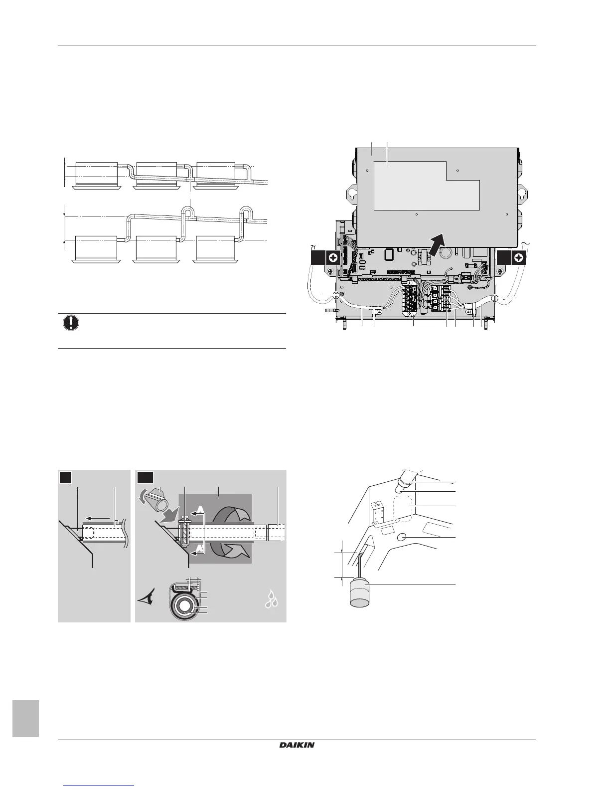
A ≤645mm: In case of installation with BYFQ60B
≤630mm: In case of installation with BYFQ60C
B 205mm: In case of installation with BYFQ60B
220mm: In case of installation with BYFQ60C
a Metal clamp (accessory)
b Drain hose (accessory)
c Rising drain piping (vinyl pipe of 25mm nominal diameter
and 32mm outer diameter) (field supply)
d Hanging bars (field supply)
▪ Combining drain pipes. You can combine drain pipes. Make
sure to use drain pipes and T-joints with the correct gauge for the
operating capacity of the units.
A ≤645mm: In case of installation with BYFQ60B
≤630mm: In case of installation with BYFQ60C
a T-joint
To connect the drain piping to the indoor unit
NOTICE
Incorrect connection of the drain hose might cause leaks,
and damage the installation space and surroundings.
1 Push the drain hose as far as possible over the drain pipe
connection.
2 Tighten the metal clamp until the screw head is less than 4mm
from the metal clamp part.
3 Check for water leaks (see "To check for water leaks" on
page14).
4 Install the insulation piece (drain pipe).
5 Wind the large sealing pad (= insulation) around the metal
clamp and drain hose, and fix it with cable ties.
6 Connect the drain piping to the drain hose.
≤4 mm
A
A'
A-A'
A
A'
f
652
ce
4
ba
d
b
a
d
c
3
1
2~61
a Drain pipe connection (attached to the unit)
b Drain hose (accessory)
c Metal clamp (accessory)
d Large sealing pad (accessory)
e Insulation piece (drain pipe) (accessory)
f Drain piping (field supply)
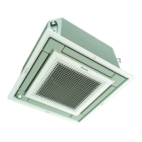
To check for water leaks
The procedure differs depending on whether electrical wiring is
already finished. When electrical wiring is not finished yet, you need
to temporarily connect the user interface and power supply to the
unit.
When electrical wiring is not finished yet
1 Temporarily connect electrical wiring.
▪ Remove the control box cover (a).
▪ Connect the single-phase power supply (50 Hz, 230 V) to
connections No. 1 and No. 2 on the terminal block for power
supply (d) and earth (c).
▪ Reattach the control box cover (a).
a Control box cover
b Inter-unit wiring
c Earth cable
d Terminal block for power supply
e Clamp
f Terminal board for transmission wiring
g Opening for cables
h Wiring diagram label (on the back of the control box lid)
i Remote controller wiring
2 Turn ON the power.
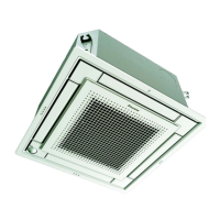
3 Start cooling operation (see "8.4 To perform a test run" on
page20).
4 Gradually pour approximately 1 l of water through the air
discharge outlet, and check for leaks.
a Plastic watering can
b Service drain outlet (with rubber plug). Use this outlet to
drain water from the drain pan.
c Drain pump location
d Drain pipe connection
e Drain pipe
5 Turn OFF the power.
6 Disconnect the electrical wiring.
▪ Remove the control box cover.
▪ Disconnect the power supply and earth.
▪ Reattach the control box cover.