6 Installation
Installer and user reference guide
13
FFA25~60A2VEB(9)
Split system air conditioners
4P550955-4 – 2018.08
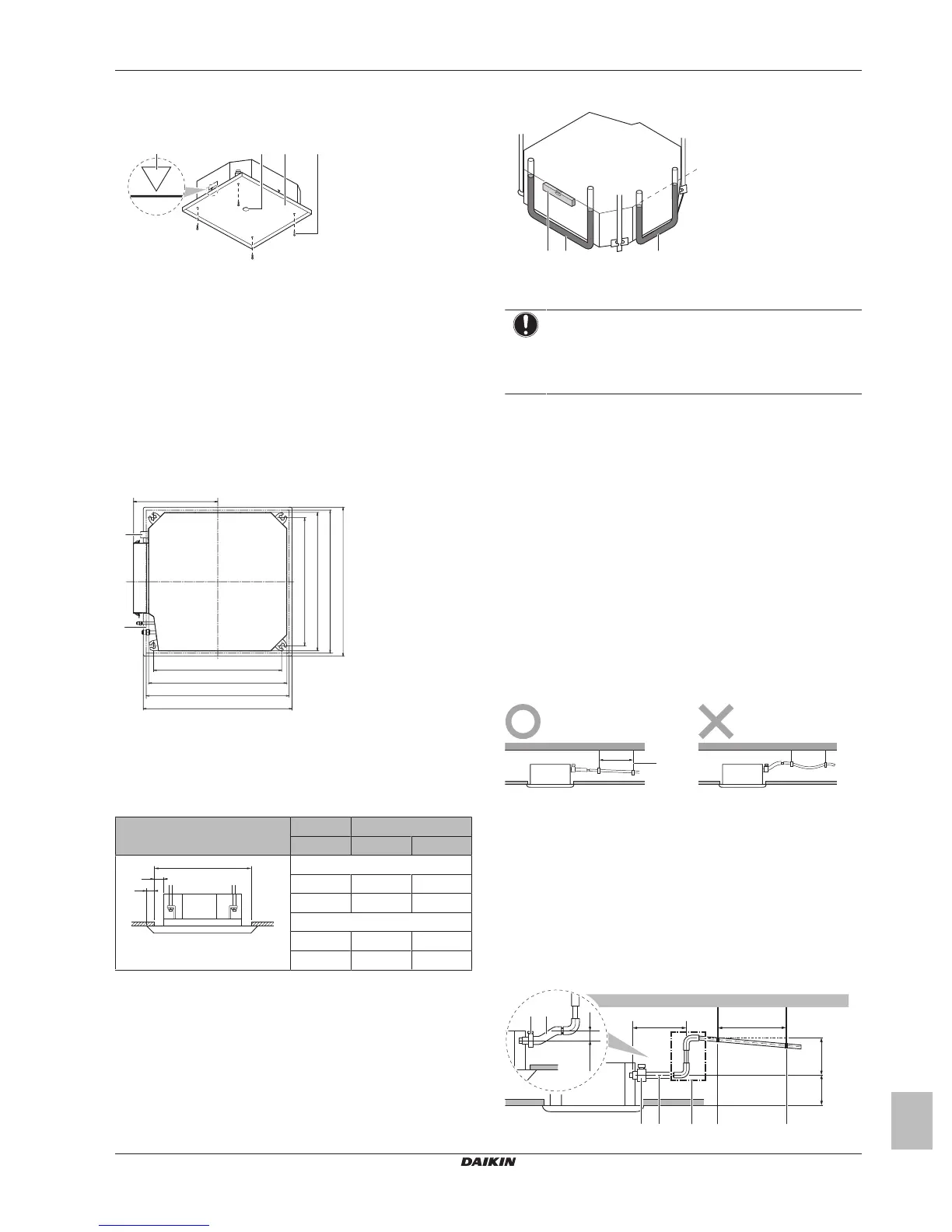
▪ Paper pattern for installation (upper part of the packing). Use
the paper pattern to determine the correct horizontal positioning. It
contains the necessary dimensions and centers. You can attach
the paper pattern to the unit.
a Centre of the unit
b Centre of the ceiling opening
c Paper pattern for installation (upper part of the packing)
d Screws (accessories)
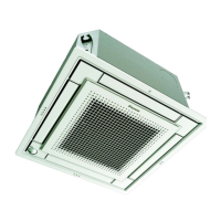
▪ Ceiling opening and unit:
▪ Make sure the ceiling opening is within the following limits:
Minimum: 585mm to be able to fit the unit.
Maximum: 660 mm in case of installation with BYFQ60B and
595 mm in case of installation with BYFQ60C ensure enough
overlapping between the decoration panel and the suspended
ceiling. If the ceiling opening is larger, add extra ceiling
material.
▪ Make sure the unit and its hanger brackets (suspension) are
centered within the ceiling opening.
(mm)
c
d
A
B
A
B
533
350
575
c
d
533
575
b
a
A 585~660mm: In case of installation with BYFQ60B
585~595 mm: In case of installation with BYFQ60C
B 700mm: In case of installation with BYFQ60B
620 mm: In case of installation with BYFQ60C
a Drain piping
b Refrigerant piping
c Hanger bracket pitch (suspension)
d Unit
Then
If A B C
BYFQ60B
≥585mm 5mm 57.5mm
≤660mm 42.5mm 20mm
BYFQ60C
≥585mm 5mm 17.5mm
≤595mm 10mm 12.5mm
A Ceiling opening
B Distance between the unit and the ceiling opening
C Overlap between the decoration panel and the suspended
ceiling
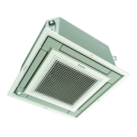
▪ Level. Make sure the unit is level at all 4 corners using a level or a
water-filled vinyl tube.
a Level
b Vinyl tube
c Water level
NOTICE
Do NOT install the unit tilted. Possible consequence: If
the unit is tilted against the direction of the condensate flow
(the drain piping side is raised), the float switch might
malfunction and cause water to drip.
6.2.3 Guidelines when installing the drain
piping
Make sure condensation water can be evacuated properly. This
involves:
▪ General guidelines
▪ Connecting the drain piping to the indoor unit
▪ Checking for water leaks
General guidelines
▪ Pipe length. Keep drain piping as short as possible.
▪ Pipe size. Keep the pipe size equal to or greater than that of the
connecting pipe (vinyl pipe of 25 mm nominal diameter and
32mm outer diameter).
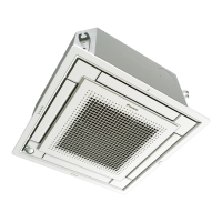
▪ Slope. Make sure the drain piping slopes down (at least 1/100) to
prevent air from being trapped in the piping. Use hanging bars as
shown.
a Hanging bar
O Allowed
X Not allowed
▪ Condensation. Take measures against condensation. Insulate
the complete drain piping in the building.
▪ Rising piping. If necessary to make the slope possible, you can
install rising piping.
▪ Drain hose inclination: 0~75 mm to avoid stress on the piping
and to avoid air bubbles.
▪ Rising piping: ≤300 mm from the unit, ≤630~675 mm
(depending on the decoration panel used) perpendicular to the
unit.
A
B
≤300
0~75
1000~1500
(mm)
ba
b c
a
dd