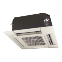
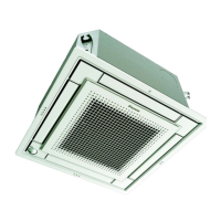
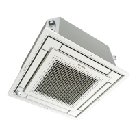
ESIE05-04 Wiring Diagrams
Part 1 – System Outline 1–83
A1P Printed circuit board Wired remote controller
C1 Capacitor (M1F) R1T Thermistor (Air)
HAP Light emitting diode (Service monitor-green) SS1 Selector switch (Main/Sub)
KAR Magnetic relay (M1S)
KPR Magnetic relay (M1P) Wireless remote controller (Receiver/display unit)
M1F Motor (Indoor fan) A2P Printed circuit board
M1P Motor (Drain pump) A3P Printed circuit board
M1S Motor (Swing flap) BS1 Push button (ON/OFF)
Q1M Thermo switch (M1F embedded) H1P Light emitting diode (on-red)
R1T Thermistor (Air) H2P Light emitting diode (timer-green)
R2T Thermistor (Coil) H3P Light emitting diode (filter sign-red)
S1L Float switch H4P Light emitting diode (defrost-orange)
S1Q Limit switch (Swing flap) SS1 Selector switch (Main/Sub)
SS1 Selector switch (Emergency) SS2 Selector switch (Wireless address set)
T1R Transformer (220~240V/22 V)
V1TR Phase control circuit Connector for optional parts
X1M Terminal block X35A Connector (Group control adaptor)
X2M Terminal block X60A, X61A Connector (Interface adaptor for Sky Air series)
RC Signal receiver circuit
TC Signal transmission circuit
 Loading...