General Outline ESIE05-04
1–6 Part 1 – System Outline
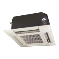
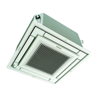
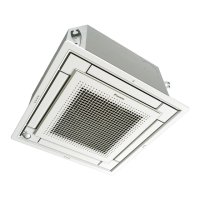
1.3 FCQ100, 125B
Outlook and
dimensions
The illustration below shows the outlook and the dimensions of the unit (mm).
Prepared hole
Branch duct
connection
or more
Installation space
REQUIRED INSTALLATION SPACE
WHEN THE DISCHARGE GRILL IS CLOSED,
THE REQUIRED SPACE IS 200 mm OR MORE.
o
r
m
o
r
e
o
r
m
o
r
e
o
r
m
o
r
e
VIEW D
Prepared hole
Branch duct
connection
Prepared hole
VIEW B
(Suspension position)
(Ceiling opening)
Branch duct
connection
or less
(Ceiling opening)
(Suspension position)
For fresh air intake kit
connection (direct
installation type)
VIEW C
Prepared hole
Hanging bolt
Adjustable
NOTES:
1. Location of the nameplates:
- Unit body: on the bell mouth at the inside of the suction grill.
- Decoration panel: on the panel frame at the inside of the suction grill.
2. When installing an optional accessory, refer to the installation drawings.
- For the fresh air intake kit ..... an inspection port is necessary
- For the high efficiency filter ..... an inspection port is necessary
- For the branch duct chamber .... an inspection port is necessary
VIEW A
Prepared hole
Branch duct
connection
o
r
m
o
r
e
see note 3
o
r
m
o
r
e
3. In case of using a wireless remote controller, this position will be a signal
receiver. Refer to the drawing of the wireless remote controller for more details.
4. When the conditions exceed 30°C and RH 80% in the ceiling or fresh air is
inducted into the ceiling, an additional insulation is required (polyethylene foam,
thickness 10mm or more).
 Loading...