ESIE05-04 General Outline
Part 1 – System Outline 1–29
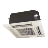
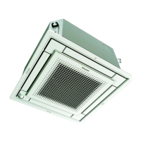
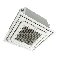
Components The table below contains the different components of the unit.
No. Component
1 Air outlet
2 Air suction grille
3Air filter
4 Gas pipe connection
5 Liquid pipe connection
6 Drain pipe connection
7 Earth terminal (Inside the electric components box)
8 Suspension bracket
9 Backward piping and wiring connection opening lid
10 Upward piping and wiring connection opening lid
11 Right side pipe connection
12 Back side drain pipe connection, left
13 Left side drain pipe connection
14 Right side drain pipe connection
15 Position of the hole in the wall for piping straight trough the wall
16 Upward drain pipe connection
17 Upward gas pipe connection
18 Upward liquid pipe connection
 Loading...