1
FHB
FHYB
FHYBP
Split System air conditioners
Operation manual
page
What to do before operation ....................................................... 1
Names and functions of parts ..................................................... 1
Name and function of each switch and
display on the remote controller .................................................. 1
Operation range .......................................................................... 2
Installation site ............................................................................ 2
Operation procedure ................................................................... 2
Optimum operation ..................................................................... 4
Not a malfunction of the air conditioner ....................................... 4
Trouble shooting ......................................................................... 5
Maintenance ............................................................................... 5
Disposal requirements ................................................................ 6
THANK YOU FOR PURCHASING THIS DAIKIN AIR CONDITIONER.
CAREFULLY READ THIS OPERATION MANUAL BEFORE USING THE AIR
CONDITIONER. IT WILL TELL YOU HOW TO USE THE UNIT PROPERLY AND HELP
YOU IF ANY TROUBLE OCCURS.
AFTER READING THE MANUAL, FILE IT FOR FUTURE REFERENCE.
WHAT TO DO BEFORE OPERATION (REFER TO FIG. 2)
This operation manual is for the following systems with standard
control. Before initiating operation, contact your Daikin dealer for the
operation manual that corresponds to your system.
If your installation has a customized control system, ask your Daikin
dealer for the operation that corresponds to your system.
1. Outdoor unit
2. Indoor unit
3. Unit with remote controller
4. Unit without remote controller (When used as simultaneous
operation)
• Heat pump type.
This system provides cooling, heating, automatic, and fan
operation modes.
• Straight cooling type.
This system provides cooling, and fan operation modes.
NAMES AND FUNCTIONS OF PARTS (REFER TO FIG. 1)
1. Indoor unit.
2. Outdoor unit.
3. Remote controller.
4. Inlet air.
5. Discharged air.
6. Refrigerant piping, connection electric wire.
7. Drain pipe.
8. Ground wire.
Wire to ground outdoor unit to prevent electrical shocks.
9. Airfilter.
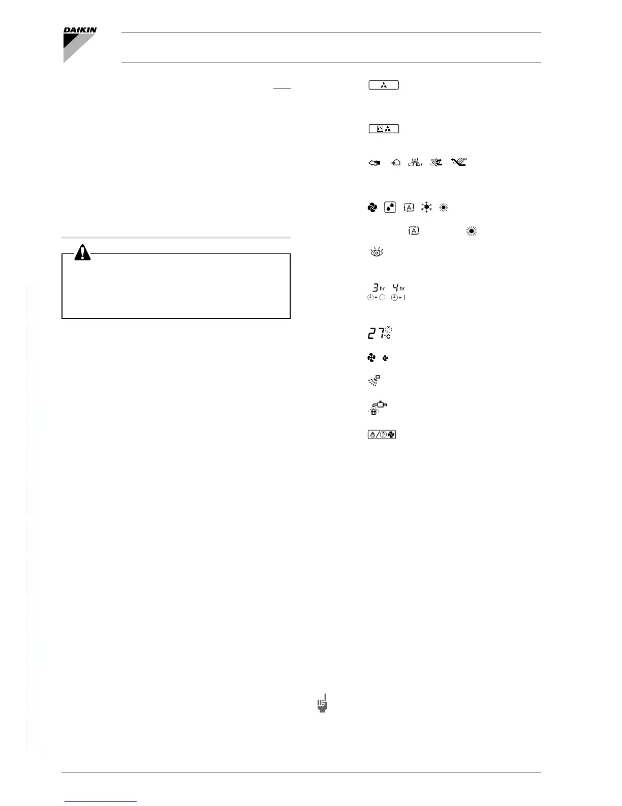
NAME AND FUNCTION OF EACH SWITCH AND
DISPLAY
ON THE REMOTE CONTROLLER (REFER TO FIG. 3)
1. ON/OFF BUTTON.
Press the button and the system will start.
Press the button again and the system will stop.
2. OPERATION LAMP (RED).
The lamp lights up during operation.
3. DISPLAY “
” (UNDER CENTRALIZED CONTROL).
When this display shows, the system is UNDER
CENTRALIZED CONTROL. (This is not a standard
specification.)
4. DISPLAY “
” (CHANGEOVER UNDER CONTROL).
This display shows when the outdoor unit is individual operation
system.
5. DISPLAY “
”, ” ” “ ” ” ” ” ” (VENTILATION/AIR
CLEANING)
This display shows that the total heat exchange and the air
cleaning unit are in operation. These are optional accessories.
6. DISPLAY “
” “ ” “ ” “ ” “ ” (OPERATION MODE)
This display shows the current OPERATION MODE. For
straight cooling type, “
” (Auto) and “ ” (Heating) are not
installed.
7. DISPLAY “
” (INSPECTION/TEST OPERATION)
When the INSPECTION/TEST OPERATION BUTTON is
pressed, the display shows the system mode is in.
8. DISPLAY “
” (PROGRAMMED TIME)
This display shows PROGRAMMED TIME of the system start
or stop.
9. DISPLAY “
” (SET TEMPERATURE)
This display shows the set temperature.
10. DISPLAY “
” (FAN SPEED)
This display shows the set fan speed.
11. DISPLAY “
” (AIR FLOW FLAP)
Refer to page 3.
12. DISPLAY “
” (TIME TO CLEAN AIR FILTER)
Refer to page 5.
13. DISPLAY “
” (DEFROST)
Refer to page 3.
14. TIMER MODE START/STOP BUTTON
Refer to page 3.
15. TIMER ON/OFF BUTTON
Refer to page 3.
16. INSPECTION/TEST OPERATION BUTTON
This button is used only by qualified service persons for
maintenance purposes.
17. PROGRAMMING TIME BUTTON
Use this button for programming “START and/or STOP” time.
18. TEMPERATURE SETTING BUTTON
Use this button for SETTING TEMPERATURE.
19. FILTER SIGN RESET BUTTON
Refer to page 5.
20. FAN SPEED CONTROL BUTTON
Press this button to select the fan speed, HIGH or LOW, of your
choice.
21. OPERATION MODE SELECTOR BUTTON
Press this button to select OPERATION MODE.
22. AIR FLOW DIRECTION ADJUST BUTTON
Refer to page 3.
23. NOT APPLICABLE
NOTE For the sake of explanation, all indications are shown on
the display in Figure 3 contrary to actual running
situations.
FHC
FHYC
FHYCP
FDY
FDYP