2 | Components
Service manual
82
FTXF20~71A + FTXF20~25B + FTXF20~42C + ATXF20~71A + ATXF20~42C
+ RXF20~71A + RXF20~60B + RXF20~42C + ARXF20~71A + ARXF20~42C
Split Sensira R32
ESIE18-12E – 2021.02
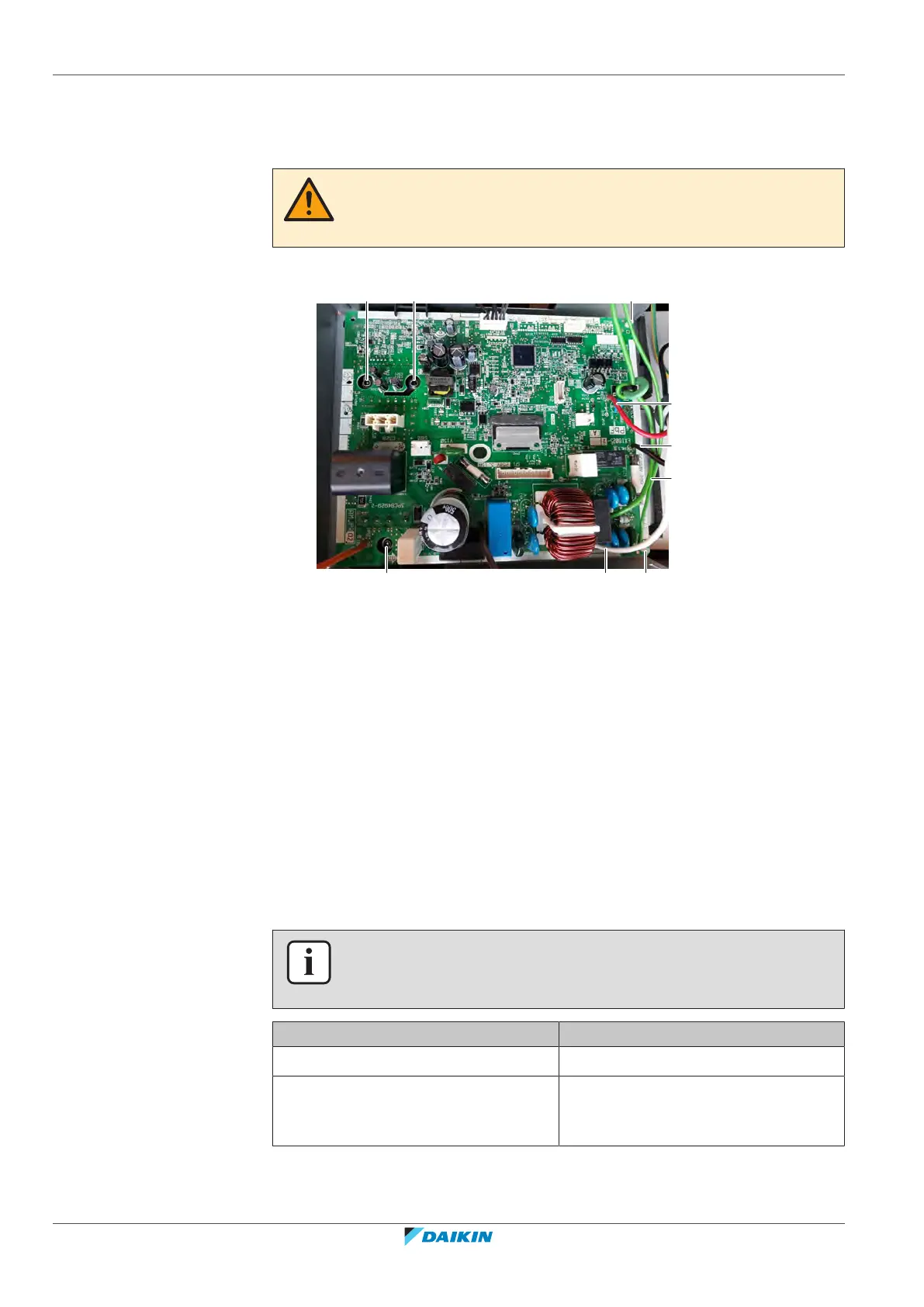
To install the main PCB
1 Apply grease to the PCB contact surface of the heat sink. Distribute the grease
as evenly as possible.
CAUTION
ALWAYS apply new grease on the PCB heat sink. NOT doing so may cause the PCB to
fail due to insufficient cooling.
2 Install the main PCB in the correct location on the PCB supports.
a Power supply wiring
b Red wire
c Ground wire
d Screw
e PCB support
3 Install and tighten the screws.
4 Route the ground wires through the ferrite core(s). Install the ground wiring
on the switch box and fix using the screw.
5 Route the reactor wires towards the reactor and connect the Faston
connectors to the reactor.
6 Route the power supply wiring through the ferrite core(s) and connect it to
the main power supply terminal X1M.
7 Route the red wire through the ferrite core(s) and connect it to the main
power supply terminal X1M.
8 Connect all connectors to the main PCB.
INFORMATION
Use the wiring diagram and connection diagram for correct installation of the
connectors, see "5.2Wiring diagram"[4142].
Is the problem solved? Action
Yes No further actions required.
No Return to "Checking procedures"[474]
of the PCB and continue with the next
procedure.
To remove a fuse of the main PCB
Prerequisite: Stop the unit operation via the user interface.