SiUS042113E Outdoor Unit
Part 3 Printed Circuit Board Connector Wiring Diagram 21
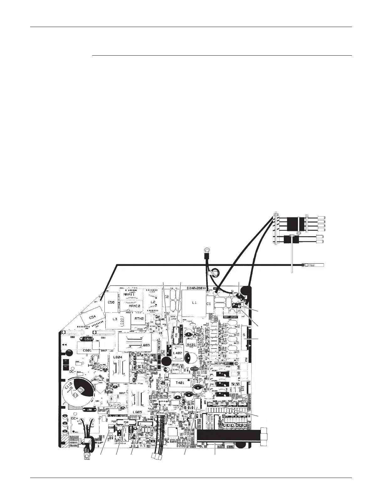
2.2 18/24 class
Main PCB (A1P)
1) S Connector for terminal block (indoor - outdoor transmission)
2) S20 Connector for electronic expansion valve coil (White)
3) S40 Connector for overload protector
4) S70 Connector for DC fan motor
5) S80 Connector for four way valve coil
6) S90 Connector for thermistors
(outdoor temperature, outdoor heat exchanger, discharge pipe,
liquid pipe)
7) S201, S202 Wire harness for service monitor PCB (A2P)
8) CK1 Wire harness for voltage endurance test
9) HL1, HN1 Wire harness for terminal block (power supply)
10) E1, E2 Wire harness for earth/ground wire
11) U, V, W Wire harness for compressor
12) FU1, FU2 Fuse (3.15 A, 250 V)
13) FU3 Fuse (30 A, 250 V)
14) V2, V3, V401 Varistor
V401
E1, E2
FU1 V3
V2
FU3
HN1
HL1
CK1
S20
S90
S201
S
S70
S202
U, V, W
FU2S80
S40
2P455785-15
 Loading...