EasyManua.ls Logo

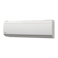
Daikin FTXR18TVJUS User Manual

Daikin FTXR18TVJUS
299 pages
To Next Page IconTo Next Page
Page #1 background imageLoading...
Page #1 background image
[Applied Models]
Inverter Pair : Heat Pump
Multi-Split Type Air Conditioners
5MXS-T, 4MXL-T Series
Service
Manual
SiUS121827E

Table of Contents

Other manuals for Daikin FTXR18TVJUS

Questions and Answers:

Daikin FTXR18TVJUS Specifications

General IconGeneral
SeriesFTXR
Cooling Capacity18, 000 BTU/h
EER (Cooling)12.5
RefrigerantR-32
Indoor Unit Weight33 lbs
Heating Capacity20, 000 BTU/h
Power Supply208/230V, 1Ph, 60Hz
Indoor Noise Level19 dB(A)

Summary

2. Functions

1. Specifications

1. Indoor Unit

6. Outdoor Unit

1. Common Functions

1.1 Temperature Control

Defines room, set, thermistor, and target temperatures for control.

1.2 Frequency Principle

Explains compressor frequency control based on load and temperature differences.

2. RA Indoor Unit Functions

3. SA Indoor Unit Functions

4. Control Specification

4.1 Thermistor Functions

Details the function and location of various thermistors used for control.

4.3 Frequency Control

Describes compressor frequency determination based on capacity and room conditions.

4.5 Discharge Pipe Temperature Control

Controls frequency to maintain discharge pipe temperature and prevent rising.

4.6 Input Current Control

Sets frequency upper limit based on input current to protect the compressor.

4.7 Freeze-up Protection Control

Prevents indoor heat exchanger freezing during cooling by limiting frequency.

4.13 Electronic Expansion Valve Control

Covers various controls for electronic expansion valve operation.

4.14 Malfunctions

Detects sensor malfunctions, overcurrent, refrigerant shortage, and anti-icing.

7. BRC1E73 Wired Remote Controller

1. General Problem Symptoms and Check Items

2. Troubleshooting with LED

2.1 Indoor Unit

Details error detection based on the indoor unit operation lamp blinking.

2.2 Outdoor Unit

Describes LED indications on the outdoor unit PCB for error detection.

3. Service Diagnosis

4. Code Indication on Remote Controller

5. Troubleshooting for RA Indoor Unit

5.1 Indoor Unit PCB Abnormality

Troubleshooting steps for abnormal indoor unit PCB (Error Code A1).

5.2 Freeze-up Protection Control/Heating Peak-cut Control

Troubleshooting for freeze-up and heating peak-cut control issues (Error Code A5).

5.3 Indoor Fan Motor or Related Abnormality

Troubleshooting for DC motor fan abnormalities (Error Code A6).

5.4 Thermistor or Related Abnormality

Troubleshooting for thermistor errors (Error Codes C4, C9).

5.6 Signal Transmission Error (Between Indoor Unit and Outdoor Unit)

Troubleshooting signal transmission errors between indoor and outdoor units (Error Code U4).

5.7 Mismatching of Indoor Unit and Outdoor Unit

Troubleshooting improper indoor/outdoor unit combinations (Error Code UA).

6. Troubleshooting for SA Indoor Unit

6.1 Indoor Unit PCB Abnormality

Troubleshooting steps for abnormal indoor unit PCB (Error Code A1).

6.2 Drain Level Control System Abnormality

Troubleshooting drain level control system issues (Error Code A3).

6.3 Indoor Fan Motor or Related Abnormality

Troubleshooting for DC motor fan abnormalities (Error Code A6).

6.4 Indoor Fan PCB Abnormality

Troubleshooting for indoor fan PCB abnormalities (Error Code A8).

6.6 Thermistor or Related Abnormality

Troubleshooting thermistor errors (Error Codes C4, C5, C9).

6.8 Remote Controller Thermistor Abnormality

Troubleshooting remote controller thermistor issues (Error Code CJ).

6.9 Signal Transmission Error (Between Indoor and Outdoor Unit)

Troubleshooting signal transmission errors between indoor and outdoor units (Error Code U4).

6.10 Signal Transmission Error (Between Indoor Unit and Remote Controller)

Troubleshooting signal transmission errors between indoor and remote controllers (Error Code U5).

6.12 Mismatching of Indoor Unit and Outdoor Unit

Troubleshooting improper indoor/outdoor unit combinations (Error Code UA).

7. Troubleshooting for Outdoor Unit

7.1 Refrigerant Shortage

Troubleshooting refrigerant shortage detection and conditions (Error Code U0).

7.2 Low-voltage Detection or Over-voltage Detection

Troubleshooting voltage detection errors (Error Code U2).

7.5 Anti-icing Control for Indoor Unit

Troubleshooting indoor unit anti-icing control issues (Error Code A5).

7.6 Outdoor Unit PCB Abnormality

Troubleshooting abnormal outdoor unit PCB operation (Error Code E1).

7.7 OL Activation (Compressor Overload)

Troubleshooting compressor overload detection (Error Code E5).

7.8 Compressor Lock

Troubleshooting compressor lock detection (Error Code E6).

7.9 DC Fan Lock

Troubleshooting DC fan lock detection (Error Code E7).

7.10 Input Overcurrent Detection

Troubleshooting input overcurrent detection (Error Code E8).

7.11 Four Way Valve Abnormality

Troubleshooting four way valve abnormalities (Error Code EA).

7.12 Discharge Pipe Temperature Control

Troubleshooting discharge pipe temperature control issues (Error Code F3).

7.13 High Pressure Control in Cooling

Troubleshooting high pressure control in cooling operation (Error Code F6).

7.16 Thermistor or Related Abnormality (Outdoor Unit)

Troubleshooting thermistor errors for outdoor units (Error Codes H9, J3, J6, J8, J9, P4).

8. Check

1. Pump Down Operation

2. Forced Cooling Operation

3. Wiring Error Check Function

4. Trial Operation

5. Field Settings

6. Silicone Grease on Power Transistor/Diode Bridge

1. Piping Diagrams

2. Wiring Diagrams

3. Outdoor Unit

4. Operation Limit

Related product manuals