English 12
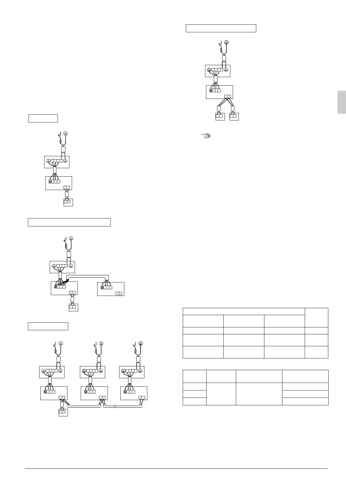
9. WIRING EXAMPLE
For the wiring of outdoor units, refer to the installation manual
attached to the outdoor units.
Confirm the system type.
•Pair type:1 remote controller controls 1 indoor unit (stan-
dard system).
• Simultaneous operation system:1 remote controller con-
trols 2 indoor units
(2 indoor units operates
equally.)
• Group control: 1 remote controller controls up to 16 indoor
units
(All indoor units operate according to the
remote controller).
• 2 remote controller control: 2 remote controller control 1
indoor unit.
NOTE
1. All transmission wiring except for the remote controller wires
is polarized and must match the terminal symbol.
2. When BRC1B517 is connected, use shield wire in transmis-
sion wiring. Ground the shield of the shield wire, at the
grounding screw of the remote controller cord grounding ter-
minal inside the control box.
3. In case of group control, perform the remote controller wir-
ing to the master unit when connecting to the simultaneous
operation system. (wiring to the slave unit is unnecessary)
4. For group control remote controller, choose the remote con-
troller that suits the indoor unit which has the most functions
(as attached swing flap).
5. For simultaneous operation system, connect the remote
controller cord to the master unit.
10. FIELD SETTING
Field settings must be made from the remote controller
and in accordance with installation conditions.
• Settings can be made by changing the “Mode No.”, “FIRST
CODE NO.” and “SECOND CODE NO.”.
• For setting procedures and instructions, see “Field settings”
provided with the remote controller.
10-1 Setting ceiling height
• Select the SECOND CODE NO. that corresponds to the
ceiling height. Refer to Table 5 and 6.
(SECOND CODE NO. is factory set to “01” for a ceiling
height of less than 2.7m.)
Table 5
Table 6
10-2 Settings for options
• For settings for options, see the installation instructions
provided with the option.
10-3 Setting air discharge direction
• For changing air discharge direction to 2-way or 3-way
air discharge, change the SECOND CODE NO. as
shown Table 7.
(SECOND CODE NO. is factory set to “01” for a air dis-
charge direction of 4-way air discharge.)
123
P1 P2
123
P1 P2
Main power supply
Main switch
Fuse
Outdoor unit
Indoor unit
Remote
controller
(Optional accessories)
Pair type
123
P1 P2
123
P1 P2
123
P1 P2
Main power supply
Main switch
Fuse
Outdoor unit
Indoor unit
(Master)
Indoor unit (Slave)
Remote
controller
(Optional accessories)
Simultaneous operation system
P1 P2
123
123
P1 P2
P1 P2 P1 P2
123
123
123
123
Main power supply Main power supply Main power supply
Main switchMain switchMain switch
FuseFuse Fuse
Outdoor unit
Indoor unit
Outdoor unit
Indoor unit
Outdoor unit
Indoor unit
Remote controller (Optional accessories)
Group control
Ceiling height (m)
Setting
4-way air dis-
charge
3-way air dis-
charge
2-way air dis-
charge
Less than 2.7m Less than 3m Less than 3.5m N
More than 2.7m;
3m or less
More than 3m;
3.5m or less
More than 3.5m;
3.8m or less
H
More than 3m;
3.5m or less
More than 3.5m;
3.8m or less
—S
Setting Mode No. FIRST CODE NO.
SECOND CODE
NO.
N
13 (23) 0
01
H02
S03
P1 P2 P1 P2
P1 P2
123
123
Main power supply
Main switch
Fuse
Outdoor unit
Indoor unit
Remote
controller
(Optional
accessories)
Remote
controller
(Optional
accessories)
2 remote controller control
01_EN_3P249378-5G.fm Page 12 Friday, January 20, 2012 2:01 PM
 Loading...