FWD
Ducted fan units
4PW17549-3
Installation and operation manual
Read this manual attentively before starting up the unit. Do
not throw it away. Keep it in your les for future reference.
Improper installation or attachment of equipment or acces-
sories could result in electric chock, short-circuit, leaks, re
or other damage to the equipment. Be sure only to use ac-
cessories made by Daikin which are specically designed
for the use with the equipment and have them installed by a
professional.
If unsure of installation procedures or use, always contact
your Daikin dealer for advice and information.
Installation and maintenance should be carried out by technical person-
nel qualied for this type of machine, in compliance with current safety
regulations.
When receiving the unit please check its state, verifying if any damage
occurred during transport.
Refer to the relevant technical sheets for installation and use of possible
accessories.
Identify model and version of the unit from the indications stated on the
carton package.
Daikin shall not be held liable
- if the unit has been installed by non-qualied personnel,
- if the unit has been used improperly,
- if the unit has been used under conditions that are not permitted,
- if maintenance operations specied in this manual have not been
carried out,
- if non original spare parts have been used.
Keep the unit in its packaging until it is ready to be installed, to prevent
dust getting inside.
Air sucked by the unit must always be ltered. Always use the supplied
air lter.
If the unit is not used during winter, drain the water from the system to
prevent damage caused by the formation of ice. If antifreeze solutions
are used, check the freezing point.
Do not change the internal wiring or other parts of the unit.
Operating limits are shown here below; all other uses are considered
improper:
• thermal carrier: water/glycol
• water temperature: 5°C~95°C
• maximum operating pressure: 10 bar
• air temperature: –20°C~43°C
• voltage tolerance: ±10%
• ambient air humidity limit: RH < 85 % non-condensing
Selection of location:
Equipment designed for ambient air conditioning and intended for use in civil
comfort applications
• do not install the unit in rooms where inammable gases are pre-
sent
• do not let water spray directly on the unit;
• install the unit on ceilings or walls that bear its weight. Leave enou-
gh space all around for proper operation and maintenance of the
unit, taking into account all installed optional accessories.
• never place the heating unit immediately under an electric plug-so-
cket.
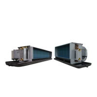
description of the eqUipment
The FWD range of air conditioning and hot-air heating units has been
implemented for conditioning rooms that require the installation of
ducted units.
Main components
• Load bearing structure made of galvanized steel sheet of suitable
thickness, duly insulated with noise-proof/anti-condensing mate-
rial, self-extinguishing in class 1. Complete with inspection panels.
• Fan unit with single or dual fan wheel, dual intake centrifugal type,
with statically and dynamically balanced impellers, coupled directly
to the 3-speed electric motor, equipped with permanently t con-
denser and thermal safety device
• Terminal strip.
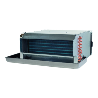
• Heat exchanger: high efciency, made of copper tube and aluminium
ns secured to the tubes by mechanical expansion. They are t
with brass manifolds and contain air valves. The heat exchanger,
normally supplied with left-hand attachments, may be turned 180°.
• System for collecting and discharging condensate, setup either for cei-
ling or wall mounting. All FWD range models may be installed ei-
ther in a horizontal or in a vertical position.
• Air intake module with air filter
• Air intake module
Made of galvanised steel sheet. These modules permit to lter the
air sucked up by the unit and also to connect the unit to the intake
channelling.
• Air filter
Made of acrylic material, self-extinguishing in class 1, with ltering
class EU 2.
The lter may be inserted or removed and is xed by means of 2
knobs with M4 threaded stems.
The ltering material may be washed and regenerated to maintain
the rated ltering efciency with limited charge leaks.
• The accessory kit comprises
- Load-bearing structure made of galvanised steel sheet
- Removable cassette-type lter (to be pulled out like a drawer)
- Self-tapping xing screws
Example for installation
(See gure 1)
1
FWD unit
2
Intake module with air lter
Installation and
operation manual
Ducted fan coil unitsFWD
 Loading...