EDUS39-600-F6 Installation
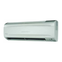
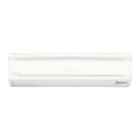
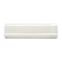
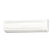
FXAQ-M 25
4. INDOOR UNIT INSTALLATION
• Use only specification-designated accessories and parts.
CAUTION
• Install so that the unit does not tilt to either side or forward.
• Do not hold the unit by the horizontal flaps when lifting it as doing so may damage the horizontal flaps.
(1) Open the piping through-hole.
• The refrigerant pipe and drain pipe can be passed through in one of 5 directions: left, bottom-left, back-left,
bottom-right, and back-right. (Refer to Fig. 3)
• Using the paper pattern for installation (3), choose where to pass the piping out and open a through-hole (φ3 1/8” /
28.6 mm) in the wall.
Open the hole so that there is a downward slope for the drain piping. See Section 6. DRAIN PIPING WORK on
Page 227.
(2) Remove the installation panel (1) from the unit and attach to the wall.
The installation panel is temporarily attached to the unit with a screw if a 12 type.
(Refer to Fig. 3)
(a) Check the location for the hole using the included paper pattern for installation (3).
• Choose a location so that there is at least a 3 1/2” (89 mm) gap between the ceiling and the main unit.
(b) Temporarily attach the installation panel (1) at the temporary-securing position on the paper pattern for
installation (3) and use a level to make sure the drain hose is either level or tilted slightly downward.
(c) Secure the installation panel (1) to the wall using either screws or bolts.
• If using the attachment screws for the installation panel (2), attach using at least 4 screws on either side (for a
total of 8 screws (07, 09, 12 type), 9 screws (18, 24 type)) of the recommended installation cleat position on
the included paper pattern for installation (3).
• If using bolts, attach using a M8 - M10 bolt or equivalent (for a total of 2 bolts) on either side.
• If dealing with concrete, use commercially available foundation bolts (M8 - M10 or equivalent).
(3) If using the left, bottom-left, or bottom-right positions for the piping, cut out the through-hole for the piping in
(4) the front grill. (Refer to Fig. 4)
(5) Remove the front panel and the service lid using the following steps and referring to Figure 5:
(1) Open the front panel to the point where it stops.
(2)
Push the axes on either side of the front panel towards the center of the main unit and remove. (You can also
remove it by sliding the front panel either to the left or right and pulling it forward.)
Installation panel (1)
Temporary screw
(In case of 12 type)
Left pipe
Back-left pipe
Back-right pipe
Bottom-left pipe
Bottom-right pipe
Front grill
Cut out along
the groove.
Cut away
Fig. 3 Fig. 4
 Loading...