English 4
• Install the indoor and outdoor units, power supply wiring,
remote controller wiring and transmission wiring at least 1
meter away from televisions or radios to prevent image inter-
ference or noise.
(Depending on the radio waves, a distance of 1 meter may
not be sufficient to eliminate the noise.)
• Install the indoor unit as far as possible from fluorescent
lamps.
If a wireless remote controller kit is installed, the transmission
distance may be shorter in a room where an electronic lighting
type (inverter or rapid start type) fluorescent lamp is installed.
(2) Use hanging bolts for installation.
Investigate if the installation place can withstand the mass
of the indoor unit and, if necessary, hang the indoor unit
with bolts after it is reinforced by beams etc. (Refer to the
installation pattern paper (5) for the mounting pitch.).
(3) Ceiling height
This indoor unit can be installed up to 4.3m (for 35-71
model, 3.5m) of the ceiling.
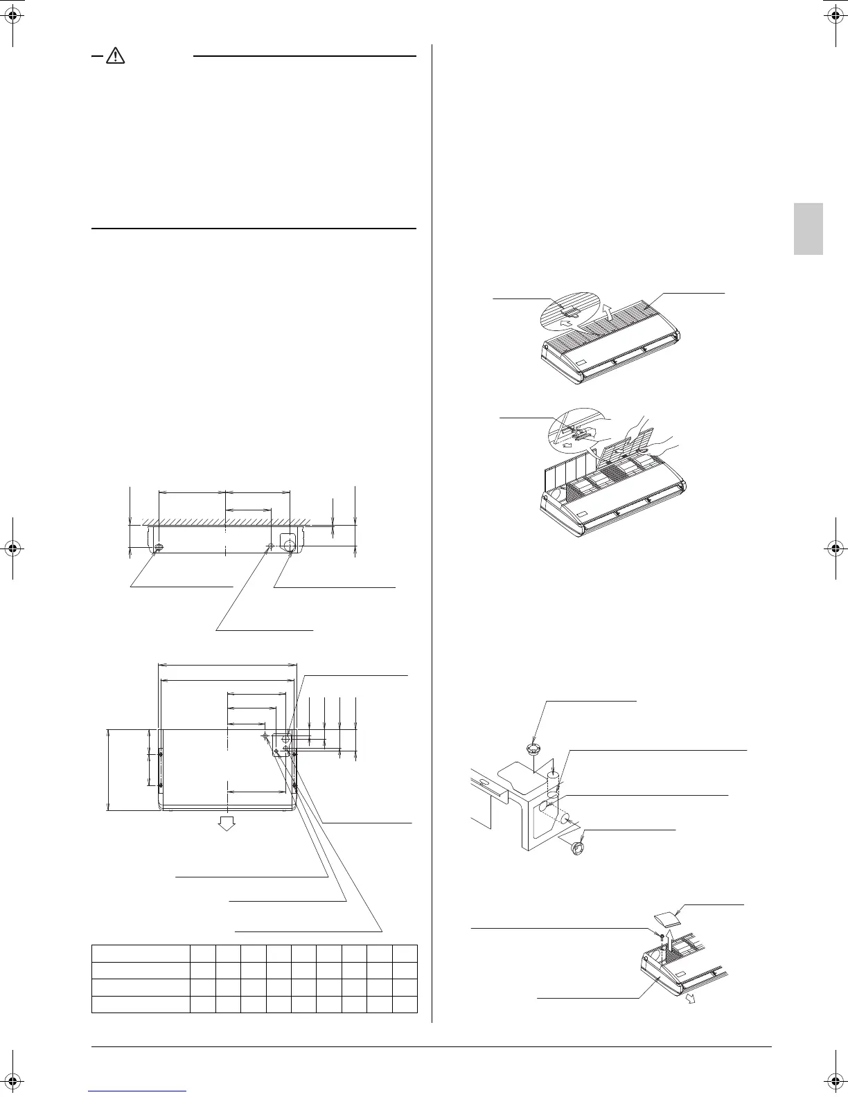
4. PREPARATION BEFORE INSTALLATION
(1) For the locations of indoor unit hanging bolts, piping
outlet holes, drain piping outlet hole, and electric wir-
ing inlet hole. (Refer to Fig. 3)
(2) Make holes for hanging bolts, piping outlet, drain pip-
ing outlet, and electric wiring inlet.
• Use the installation pattern paper (5).
• Determine the locations of hanging bolts, piping outlet,
drain piping outlet and electric wiring inlet. And make the
hole.
(3) Remove the parts of the indoor unit.
1) Remove the suction grille.
• Slide the suction grille fixing knobs (35, 50 type: 2
places for each, 60~140 type: 3 places for each) toward
backward direction (as shown by an arrow) to open the
suction grille widely. (Refer to Fig. 4)
• Keeping the suction grille opened, hold the knob at the
back of the suction grille and at the same time, pull the
suction grille forward to remove. (Refer to Fig. 5)
2) Remove the decoration side panel (right, left).
• Remove the fixture screw of the decoration side panel
(one for each), pull forward (arrow direction) to remove.
(Refer to Fig. 6)
• Take out accessories. (Refer to Fig. 6)
• Open the knock hole at the wiring inlet side at the rear
surface or top surface, and install the attached resin
bushing (10).
Model name (FHQ-) A B C D E F G H J
Type 35 · 50 960 920 378 324 270 375 398 377 260
Type 60 · 71
1270 1230
533 479 425 530 553 532 415
Type 100 · 125 · 140
1590 1550
693 639 585 690 713 692 575
GH
J
5
175
200
View from the front
Left back drain
piping outlet hole
Wall hole for back side
piping outlet
(φ100 hole)
Back side wiring
outlet location
Fig. 3
F
690 Unit dimension
210
D
A Unit dimension
B Hanging bolt pitch
View from
the ceiling
260
30
163
E
189
87
C
Discharge
Unit : mm
Top panel drain piping
connection position
Top panel gas side
piping connection
position
Top panel liquid side piping
connection positions
Top panel wiring outlet position
Hanging bolt (4 pieces)
Hanging bolt pitch
Fig. 4
Fig. 5
Fixing knob
Suction grille
Rear knob
Resin bushing (10)
(accessory)
Removable part
(for leading in from the upward-facing)
Resin bushing (10)
(accessory)
Removable part
(for leading in from the rear-facing)
Fig. 6
Fixing screw for decoration side Panel
(M4)
Decoration side panel
Accessories
01_EN_3P368557-1.fm Page 4 Wednesday, December 10, 2014 10:31 AM
 Loading...