3
• VRV® Systems • Indoor Unit
13
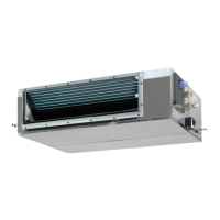
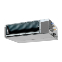
• Indoor Unit • Round Flow Cassette • FXSQ-P
6 Dimensional drawings
FXSQ20-32P
3TW31184-1A
NOTE
1 Refer to ‘outlook drawing for installing optional accessories’
when installing optional accessories.
2 The required ceiling depth varies according to the
configuration of the specific system.
3 For maintenance of the air filter, it is necessary to provide a
service access panel.
Refer to the ‘filter installation method’ drawing.
Nr Name Description
1Liquid pipe connection ø 6.35 flare (connection)
2Gas pipe connection ø 12.70 (flare connection)
3Drain pipe connection
VP20 (O.D. ø 32 /I.D. ø 25)
4 Remote control wiring connection
5 Power supply connection
6 Drain hole VP25 (OD
ø 32 /I.D. ø 25
)
7Air filter
8 Air suction side
9 Air discharge side
10 Nameplate
View A-A Detail B
Suspension bolt
(Service space)
Detail B
350 or more
(Service space)
(Suspension position)
(Suspension position)
FXSQ40-50P
3TW31214-1A
NOTE
1 Refer to ‘outlook drawing for installing optional
accessories’ when installing optional accessories.
2 The required ceiling depth varies according to the
configuration of the specific system.
3 For maintenance of the air filter, it is necessary to
provide a service access panel.
Refer to the ‘filter installation method’ drawing.
Nr Name Description
1Liquid pipe connection ø 6.35 flare (connection)
2Gas pipe connection ø 12.70 (flare connection)
3 Drain pipe connection VP25 (O.D. ø 32 /I.D. ø 25)
4 Remote control wiring connection
5 Power supply connection
6 Drain hole VP25 (OD
ø 32 /I.D. ø 25
)
7 Air filter
8 Air suction side
9 Air discharge side
10 Nameplate
View A-A
Detail B
Suspension bolt
(Service space)
Detail B
350 or more
(Service space)
(Suspension position)
(Suspension position)
or more
 Loading...