EasyManua.ls Logo

Daikin GQI-Eco Series User Manual

Daikin GQI-Eco Series
215 pages
To Next Page IconTo Next Page
Page #1 background imageLoading...
Page #1 background image
Service Manual
GQI-Eco Series
Heat Pump R-410A 50Hz
Smart RZQG71~140L9V1
RZQG71~125L9Y1 / RZQG140LY1
Classic RZQSG71L3V1 / RZQSG100~140L9V1
RZQSG100~125L8Y1 / RZQSG140LY1
ESIE15-13B

Table of Contents

Questions and Answers:

Daikin GQI-Eco Series Specifications

General IconGeneral
BrandDaikin
ModelGQI-Eco Series
CategoryHeat Pump
LanguageEnglish

Summary

1. Introduction

1.1 Version log

Records changes and updates made to the manual across different versions.

1.2 Safety Cautions

Essential safety instructions before performing repair work.

1.2.2 Cautions Regarding Safety of Users

1.3 Used Icons

1.4 Preface

Part 1 General Information

1. Model Names of Indoor / Outdoor Units

Lists the various indoor and outdoor unit model names.

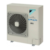
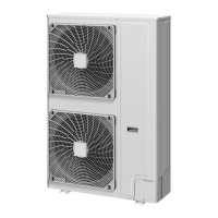
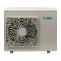
2. Outlook Outdoor Units

3. Operating range

3.1 Smart

Operating temperature range for the Smart series units.

3.2 Classic

Operating temperature range for the Classic series units.

3.3 EDP

Operating temperature range for the EDP series units.

Part 2 Remote Controller

1. Wired Remote Controller

Details about wired remote controllers.

1.1 Applicable Models

Lists models compatible with wired remote controllers.

1.2 Names and Functions

Describes the names and functions of buttons and indicators.

1.2.2 BRC1E52/53

Details the BRC1E52/53 wired remote controller buttons and functions.

1.2.1 BRC1D528

1.3 MAIN/SUB Setting when Using 2 Remote Controllers

1.3.1 BRC1D528

Procedure for setting BRC1D528 as MAIN or SUB.

1.4.2 BRC1E52/53

2. Wireless Remote Controller

2.1 Applicable Models

Lists models compatible with wireless remote controllers.

2.2 Names and Functions

Explains buttons and indicators of wireless remote controllers.

3. Service Mode

3.1 BRC1D528

Service mode operations for BRC1D528.

3.1.1 Display Service Data

How to display service data like error history and sensor readings.

3.1.2 Service Setting

Performing settings in service mode for BRC1D528.

3.2 BRC1E52/53

Service mode operations for BRC1E52/53.

3.2.1 Display service data

How to display service data for BRC1E52/53.

Part 3 Function and Control

1. Function of Main Components and Thermistors

Describes the roles of key components and thermistors.

2. Operation Flow Chart

2.1 Cooling / Dry Operation

Flowchart for cooling and dry operation modes.

2.2 Heating Operation

Flowchart for heating operation mode.

3. Function Details

3.1 Indoor Unit

Details on indoor unit functions and settings.

3.1.1 Set Temperature and Control Temperature

Relationship between set and control temperatures.

3.1.2 Thermostat Control

How the thermostat regulates operation based on temperature differences.

3.1.8 Freeze-up Prevention Control

Prevents indoor heat exchanger freezing by forced thermostat off.

3.2 Outdoor Unit

3.2.1 Abnormal Stop

Conditions and criteria for abnormal outdoor unit shutdown.

3.2.5 Starting Control

How the unit starts up, controlling frequency and fan speed.

3.2.7 Compressor Step

Controls compressor frequency for constant evaporation/condensing temperatures.

3.2.8 General Electronic Expansion Valve Control

PI control of EEV to maintain subcooling degree.

3.2.9 Hot Start Control (Only in Heating Operation)

Controls indoor fan to prevent cold draft during heating startup.

3.2.10 Night-time Quiet Operation

Settings for reducing outdoor unit sound during night.

3.2.12 High Pressure Protection Control

Prevents activation of high pressure safety device.

3.2.13 Heating Control at High Outdoor Air Temperature

Controls fan speed during heating overload at high outdoor temps.

Part 4 Field Setting

1. Test Operation

Steps for performing initial operation tests.

1.1 Pre-run Checks

Checks to perform before starting the test run.

1.3 Test Run

Step-by-step guide for executing the test run.

1.4 Precautions Regarding Test Run

Important warnings and considerations before and during test run.

1.5 Failure Diagnosis at the Moment of First Installation

Troubleshooting steps for initial installation failures.

2. Field Setting from Remote Controller

2.1 Wired Remote Controller

Field setting procedures for wired remote controllers.

2.1.1 BRC1D528

Steps for field setting with BRC1D528.

2.1.2 BRC1E52

Steps for field setting with BRC1E52 (or similar).

2.1.3 Remote controller settings

Detailed table of remote controller settings and their codes.

2.2 Wireless Remote Controller

2.3 Settings Contents and Code No. for Indoor Units

Automatic Operation Mode Control

Automatic Restart after Power Failure Reset

Setting of Normal Airflow

Airflow Direction Setting

Airflow Range Setting

Individual Setting of Ventilation

2.4 Overview of the Field Setting on the Outdoor Units

2.5 Quiet (Low Noise) Operation

2.5.1 Quiet (Low Noise) Operation by Automatic Control

Automatic control for low noise operation based on temperature.

2.5.2 External Activation from Optional PCB

Activating quiet operation using an external PCB.

2.6 I-Demand Function

2.7 Setting for Low Humidity Application

3. Field Setting from Outdoor Unit PCB

3.1 Location of DIP Switch and BS Button

Identifies the location and function of DIP switches and BS buttons.

3.2 Field Setting by BS Buttons

Procedures for field setting using BS buttons.

3.2.1 Setting Mode 1

Navigating and checking status in setting mode 1.

3.2.3 Setting Mode 2

Procedures for configuring various settings in mode 2.

3.2.4 Monitor Mode

Checking operating status and error details using BS buttons.

Part 5 Service Diagnosis

1. Maintenance Inspection

Procedures for routine maintenance checks.

1.1 Overview

General overview of maintenance tasks.

2. Symptom-based Troubleshooting

2.1 Overview

Table of symptoms and corresponding troubleshooting pages.

2.2 Equipment does not Operate

Troubleshooting steps when the unit fails to start.

2.3 Indoor Unit Fan Operates, but Compressor does not Operate

Diagnosing issues when the fan runs but the compressor doesn't.

2.4 Cooling / Heating Operation Starts but Stops Immediately

Troubleshooting when operation stops shortly after starting.

2.5 After Unit Shuts Down, It cannot be Restarted for a While

Diagnosing restart issues after shutdown.

2.6 Equipment Operates but does not Provide Cooling

Troubleshooting when the unit operates but doesn't cool.

2.7 Equipment Operates but does not Provide Heating

Troubleshooting when the unit operates but doesn't heat.

2.8 Equipment Discharges White Mist

Identifying causes for white mist discharge.

2.9 Equipment Produces Loud Noise or Vibration

Diagnosing and resolving noise or vibration issues.

2.10 Equipment Discharges Dust

Troubleshooting dust discharge from the unit.

2.11 Remote Controller LCD Displays "88"

What to do when the remote controller shows "88".

2.12 Swing Flap does not Operate

Troubleshooting when the swing flap fails to move.

3. Troubleshooting by LED Indications

3.1 Troubleshooting by LED on the Indoor Unit

Interpreting indoor unit LED indicators for fault diagnosis.

4. Troubleshooting by Remote Controller

4.1 Procedure of Self-diagnosis by Remote Controller

Steps for performing self-diagnosis via remote controller.

4.1.1 Wired Remote Controller – BRC1D528

Self-diagnosis procedure for the BRC1D528 wired controller.

4.1.2 Wired Remote Controller – BRC1E51/52A7

Malfunction/warning display and corrective actions for BRC1E51/52A7.

4.1.3 Wireless Remote Controller

How to read and interpret error codes from wireless remote controllers.

4.2 Error Codes and Description

4.3 Safety Devices

4.3.1 Outdoor Unit

Safety devices used in the outdoor unit.

4.4 Indoor Unit PCB Abnormality

4.5 Drain Water Level System Abnormality

4.6 Indoor Unit Fan Motor Abnormality

4.7 Capacity Setting Abnormality

4.8 Transmission Error (between Indoor Unit PCB and Adaptor PCB)

4.9 Thermistor Abnormality

4.10 Humidity Sensor System Abnormality

4.11 Malfunction of Motion Sensor / Floor Temperature Sensor

4.12 Remote Controller Thermistor Abnormality

4.13 Outdoor Unit PCB Abnormality

4.14 High Pressure Abnormality (Detected by the High Pressure Switch)

4.15 Actuation of Pressure Sensor

4.16 Compressor Motor Lock

4.17 Outdoor Unit Fan Motor Abnormality

4.18 Electronic Expansion Valve Abnormality

4.19 Discharge Pipe Temperature Control

4.20 High Pressure Switch System Abnormality

4.21 Low Pressure Switch System Abnormality

4.22 Thermistor System Abnormality

4.23 Outdoor Unit PCB Abnormality

4.24 Radiation Fin Temperature Rise

4.25 Output Overcurrent Detection

4.26 Electronic Thermal (Time Lag)

4.27 Stall Prevention (Time Lag)

4.28 Transmission System Abnormality (between Control and Inverter PCB)

4.29 Open Phase or Power Supply Voltage Imbalance

4.30 Defective Capacity Setting

4.31 Refrigerant Shortage (Alert)

4.32 Refrigerant Shortage (Error)

4.33 Power Supply Voltage Abnormality

4.34 Transmission Error between Indoor and Outdoor Unit

4.35 Transmission Error Between Remote Controller and Indoor Unit

4.36 Transmission Error between MAIN Remote Controller and SUB Remote Controller

4.37 Field Setting Switch Abnormality

4.38 “UC” Address Duplication of Centralized Controller

4.39 Transmission Error Between Centralized Controller and Indoor Unit

4.40 Transmission Error between Indoor and Outdoor Unit / Piping and Wiring Mismatch / Refrigerant Shortage

4.41 Check

Check the Thermistors

Step-by-step guide to checking thermistors.

1. Piping Diagrams

1.1 RZQG-L9V1

Piping diagram for the RZQG-L9V1 model.

2. Wiring Diagrams

2.1 Outdoor Unit

Wiring diagrams for the outdoor unit.

2.1.1 RZQG71L

Wiring diagram specific to the RZQG71L outdoor unit.

2.1.2 RZQG100-140L

Wiring diagram specific to the RZQG100-140L outdoor unit.

3. Thermodynamic characteristic of R-410A

4. Removing the switchbox

Related product manuals