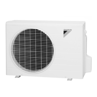
Do you have a question about the Daikin RC50RRV161 and is the answer not in the manual?
Remove the top panel by unscrewing 4 screws.
Remove front panel by 7 screws and side hooks, then discharge grille.
Pull out terminals from capacitor and terminal board, release lead wire from hook.
Remove nut securing the outdoor fan to the motor shaft.
Remove fixing frame, hooks, and screws to detach the fan motor.
Unscrew and remove right side panel and stop valve cover.
Remove wire fixture, disconnect connecting and power supply wires from terminal board.
Remove screws from the rear side and unfasten the hook on the back.
Remove the right side panel after unscrewing and unhooking.
Remove the sound blanket from the top and cut the 2 clamps.
Remove protection net and any putties present.
Heat up brazed parts and carefully remove the capillary tube.
Unscrew the nut and remove the terminal cover from the compressor.
Disconnect the compressor lead wires based on terminal patterns.
Unscrew the partition plate and the 3 nuts securing the compressor.
Heat up brazed pipes on discharge and suction sides and disconnect them.
| Model | RC50RRV161 |
|---|---|
| Display | LCD |
| Battery Type | AAA |
| Battery Quantity | 2 |
| Type | Remote Controller |
| Functions | Temperature control, mode selection, fan speed, timer |


