Table 9: Recommended Vapor and Liquid Line Sizes for Various Lengths of Run
Recommended Vapor and Liquid Line Sizes for Various Lengths of Run
Equivalent
Length to
Evaporator
(ft)
Cooling Model
Liquid Line O.D. Sizes (in) Vapor Line O.D. Sizes (in)
6 7 10 12 15 20 6 7 10 12 15 20
0 to 15 1/2 1/2 5/8 5/8 5/8 7/8 1-1/8 1-1/8 1-3/8 1-3/8 1-5/8 1-5/8
16 to 50 1/2 1/2 5/8 5/8 5/8 7/8 1-1/8 1-1/8 1-3/8 1-5/8 1-5/8 1-5/8
51 to 100 1/2 1/2 5/8 5/8 3/4 7/8 1-1/8 1-3/8 1-3/8 1-5/8 1-5/8 2-1/8
101 to 150 1/2 1/2 5/8 5/8 3/4 7/8 1-3/8 1-3/8 1-5/8 2-1/8 2-1/8 2-1/8
NOTE: Line length between condenser and evaporator (suction and liquid) not to exceed 150' equivalent length.
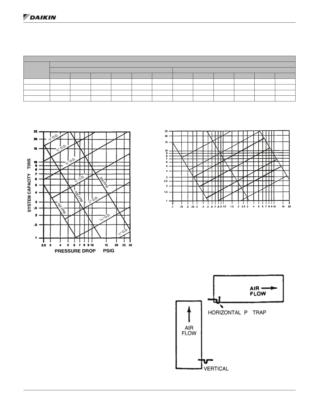
Figure 10: Liquid Line Pressure Drop Per 100 Feet
Equivalent Length (Type L Copper Tubing)
Note:
1. When evaporator coil is above condenser, the pressure
drop due to vertical lift (0.5 PSIG per foot of lift) must be
added to the pressure drop derived from this curve.
2. Size liquid line for no more than 10°F loss (approximately
30 PSIG total pressure drop).
3. Do not oversize liquid line. Oversized liquid lines add
signicantly to the amount of refrigerant required to
charge the system.
4. The maximum recommended velocity with solenoid
valves or other quick closing devices in the liquid line is
300 FPM.
Figure 11: Suction Line System Capacity Loss In Percent
Per 100 Feet Equivalent Length (Type L Copper Tubing)
Note:
1. The minimum velocity line (700 fpm) is recommended
for cooling only units with vertical or horizontal run
refrigerant lines.
2. For suction pressure drop (PSIG), multiply percent (%)
loss by 1.18.
Figure 12: Typical Drain Piping
www.DaikinApplied.com 13 IM 962-4 • AIR-COOLED SPLIT SYSTEM CONDENSERS
 Loading...