IM-790 Page 3
Operation
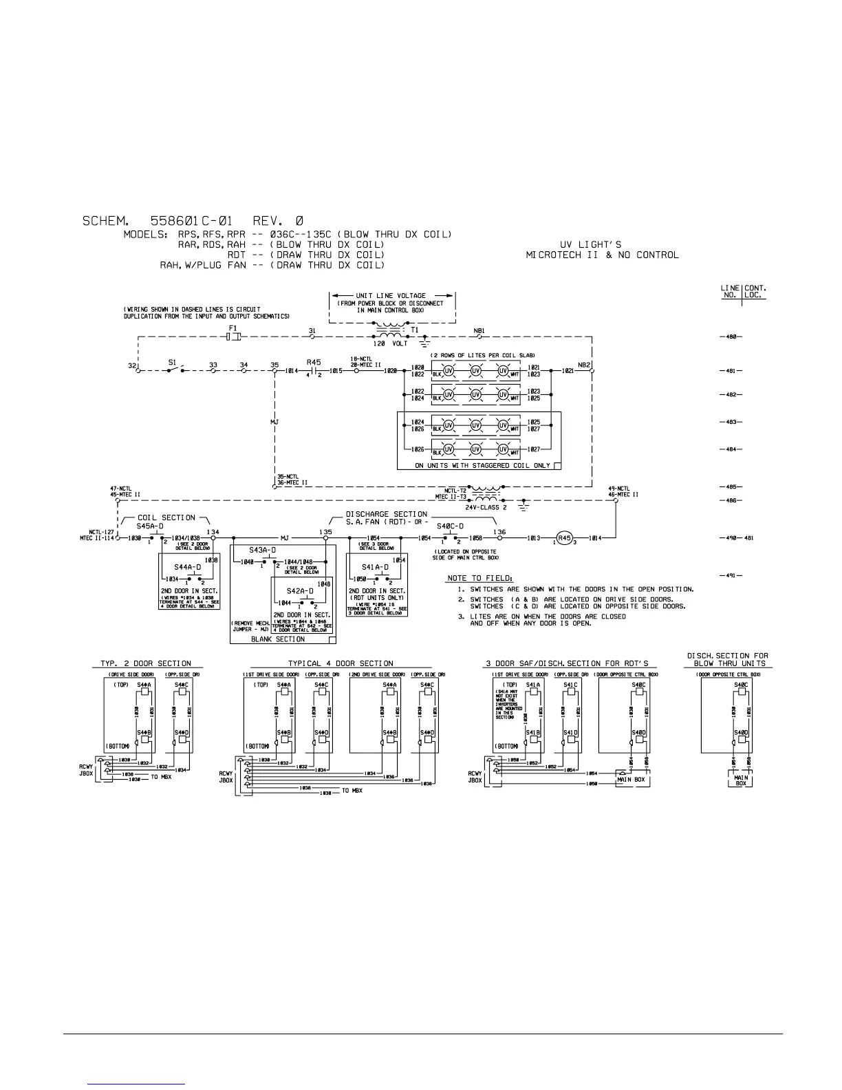
Refer to the Wiring Schematic below. 115 VAC power for the
UV lights is provided by control circuit transformer T1. The
lights operate whenever the unit is powered, system switch S1
is closed, and all doors with door power disconnect switches
are closed. To turn the lights off, disconnect power to the entire
unit, or open system switch S1.
The normally open disconnect switches are wired in series in a
circuit that supplies 24VAC to the coil of relay R45. When all
doors are closed, relay R45 is energized, and its normally open
contacts (in series with system switch S1) provide 115VAC to
the UV lights.
Figure 2. Typical Ultraviolet Light Wiring Schematic